Pump gear

a technology of pump gear and cylinder head, which is applied in the direction of positive displacement liquid engine, piston pump, liquid fuel engine, etc., can solve the problems of large disadvantages in the radial arrangement of the cylinder head, large diameter of the diaphragm pump head, and high production and storage costs, so as to improve the accessibility from one side, improve the effect of compact flat construction and increase the complexity

Active Publication Date: 2015-08-04
BRAN & LUEBBE GMBH
View PDF20 Cites 58 Cited by
  • Summary
  • Abstract
  • Description
  • Claims
  • Application Information

AI Technical Summary

Benefits of technology

[0014]In an especially preferred refinement, the three cylinder axes are only distributed over an angular range of 90°, however, and the individual cylinders are then each at an angle of 45° to one another. This arrangement allows an even more compact embodiment of the pump. The accessibility from one side is improved even further. Depending on the special requirements, for example, arrangements at angles of 30° and 60° or other angle combinations are also possible.
[0015]The pump mechanism may be driven using a worm gear pair or an external geared motor which may be coupled directly to the crankshaft. Therefore, the crankshaft has both a coupling for such an external transmission and also a connection device for a worm gear pair in a preferred refinement. If the pump mechanism is enclosed by a housing, both drive possibilities are expediently possible using the same basic variation of a housing. The worm gear pair may be integrated in the housing, while the external transmission may be mounted externally on the housing in an extension of the crankshaft. The drive motor is then either mounted laterally directly on the housing for the drive via the worm gear pair, or adjoining the housing for drive via the external transmission. A stroke frequency suitable for diaphragm pumps may be generated using both types of drive. Such a frequency is typically below 250 strokes per minute. The drive of the pump mechanism via a worm gear pair has the advantage that multiple pump mechanisms may be chained horizontally via a connection of the worm shafts. A vertical chaining of multiple mechanisms is possible with both types of drive. For this purpose, the crankshafts of multiple pumps may be coupled to one another. In this case, it is possible to position the pump heads on the same side or also alternately.
[0016]In a preferred embodiment variation of the pump mechanism having three cylinders, which enclose an angle of 90° overall, the crankshaft is driven via a worm gear pair. The drive motor, whose axis is perpendicular to the crankshaft, of course, is preferably mounted in such a way that its axis encloses an angle of less than or equal to 135° with the axis of the middle cylinder. Cylinders and drive motor are then situated in a fan shape around the crankshaft. If the worm engages on the crankshaft in proximity to the cranks, the crankshaft may be implemented as correspondingly short, and an especially compact flat construction of the pump is possible.
[0017]In all above-mentioned embodiment variations, these cylinders are each offset by one connecting rod thickness in the direction of the longitudinal axis of the crankshaft and do not lie in one plane. This may make increased complexity necessary during connection of the pump, in the piping, for example. This constructive disadvantage may be avoided in a preferred embodiment if one or more connecting rods are bent in such a way that the outer ends of all connecting rods facing away from the crankshaft lie in one plane, while the other ends are mounted next to one another and / or, with a vertical crankshaft, one on top of another on the crankshaft, of course. For a three-cylinder pump, at least two such bent connecting rods are necessary so that all connecting rod ends facing away from the crankshaft may lie in one plane. In another preferred variation, the height offset of the cylinder axes is avoided in that either the connecting rods engage off center on the crossheads or the crossheads engage off center on the pistons. In this way, the crosshead tracks, or at least the cylinder heads, may be brought into one plane. A combination of both cited measures is also expedient.
[0018]For the mounting of the connecting rods on the crankshaft, the crankshaft is preferably assembled from at least two parts along its length. The division is expediently located in the area of the cranks. The torque transmission is then ensured by a formfitting shaft-hub connection. Possible embodiments are, inter alia, a multi-tooth or polygonal profile or a feather key. A dividable crankshaft allows the use of multiple identical connecting rods, or at least connecting rods having identically shaped closed main bearings, for all cylinders. Storage and production costs may thus be lowered and / or kept low. For three-cylinder or four-cylinder pump mechanisms, the crankshaft must be assembled from at least two parts for this purpose. For a larger number of cylinders, more parts are correspondingly required.

Problems solved by technology

Since the diaphragms used therein are only capable of limited deflection, diaphragm pump heads having very large diameters are required for large delivery volumes.
High costs in production and storage result due to this and due to the large amount of space required.
The radial arrangement of the cylinders is connected to significant disadvantages, however.
Firstly, the overall pump is thus relatively protrusive, and the space required by the pump is still unsatisfactory, in addition, the accessibility of the rear cylinders is significantly restricted when the pump is installed.

Method used


Image

  • Pump gear
  • Pump gear
  • Pump gear

Examples


Embodiment Construction

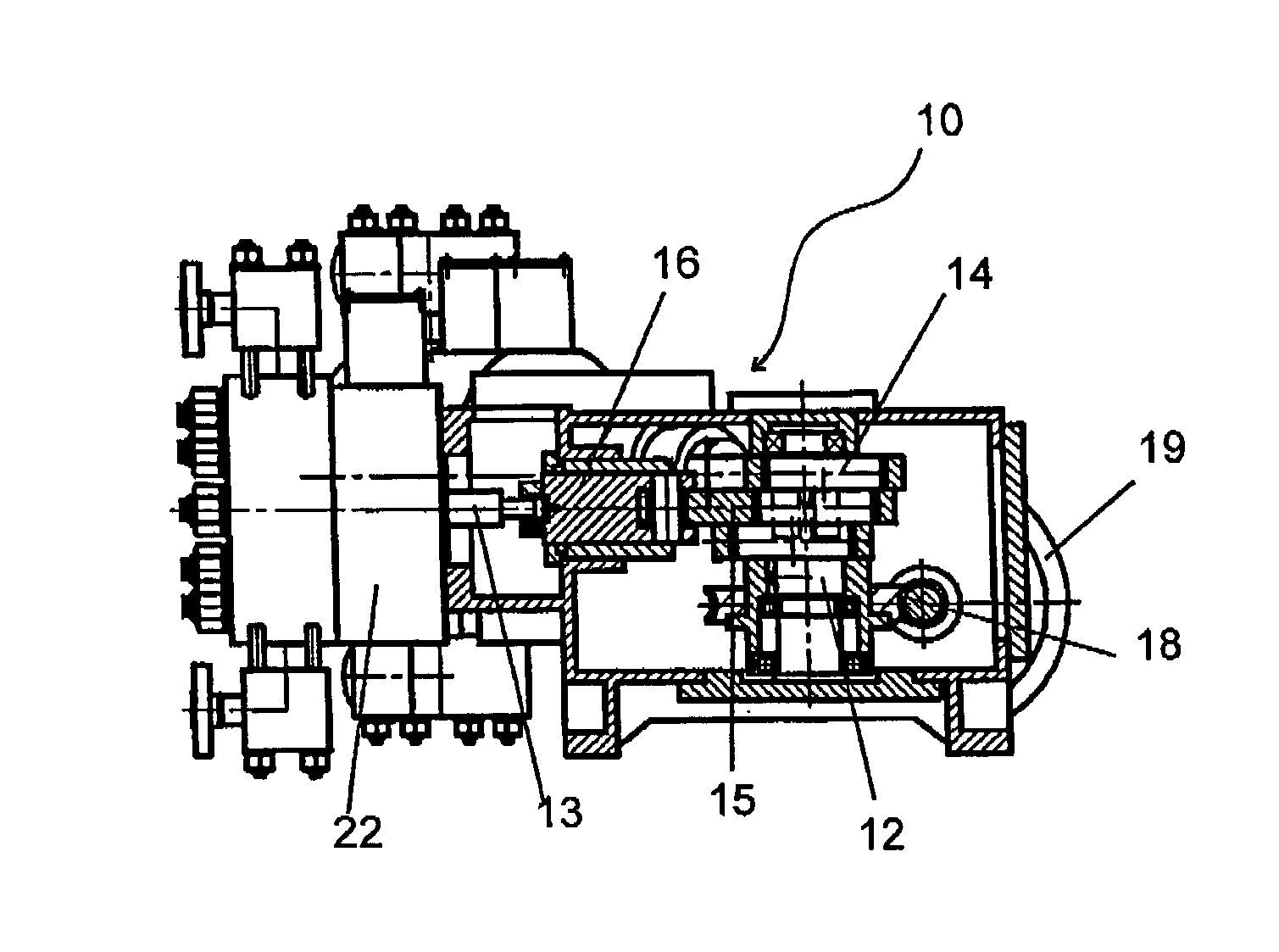
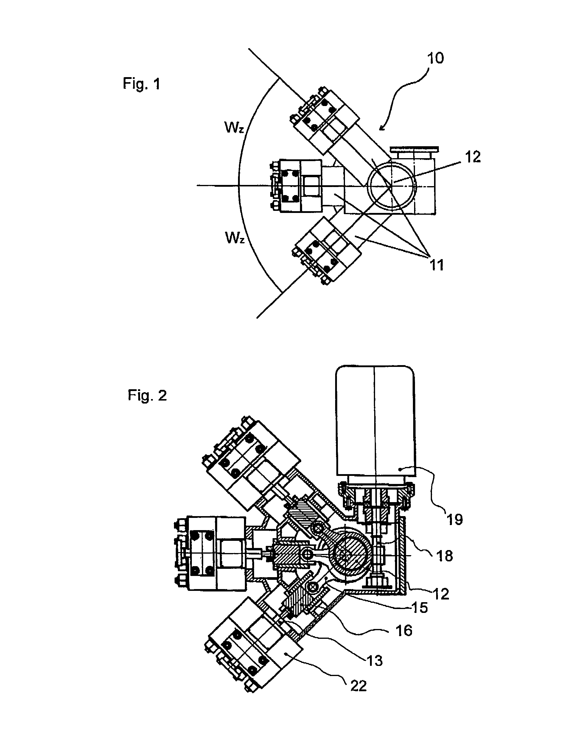
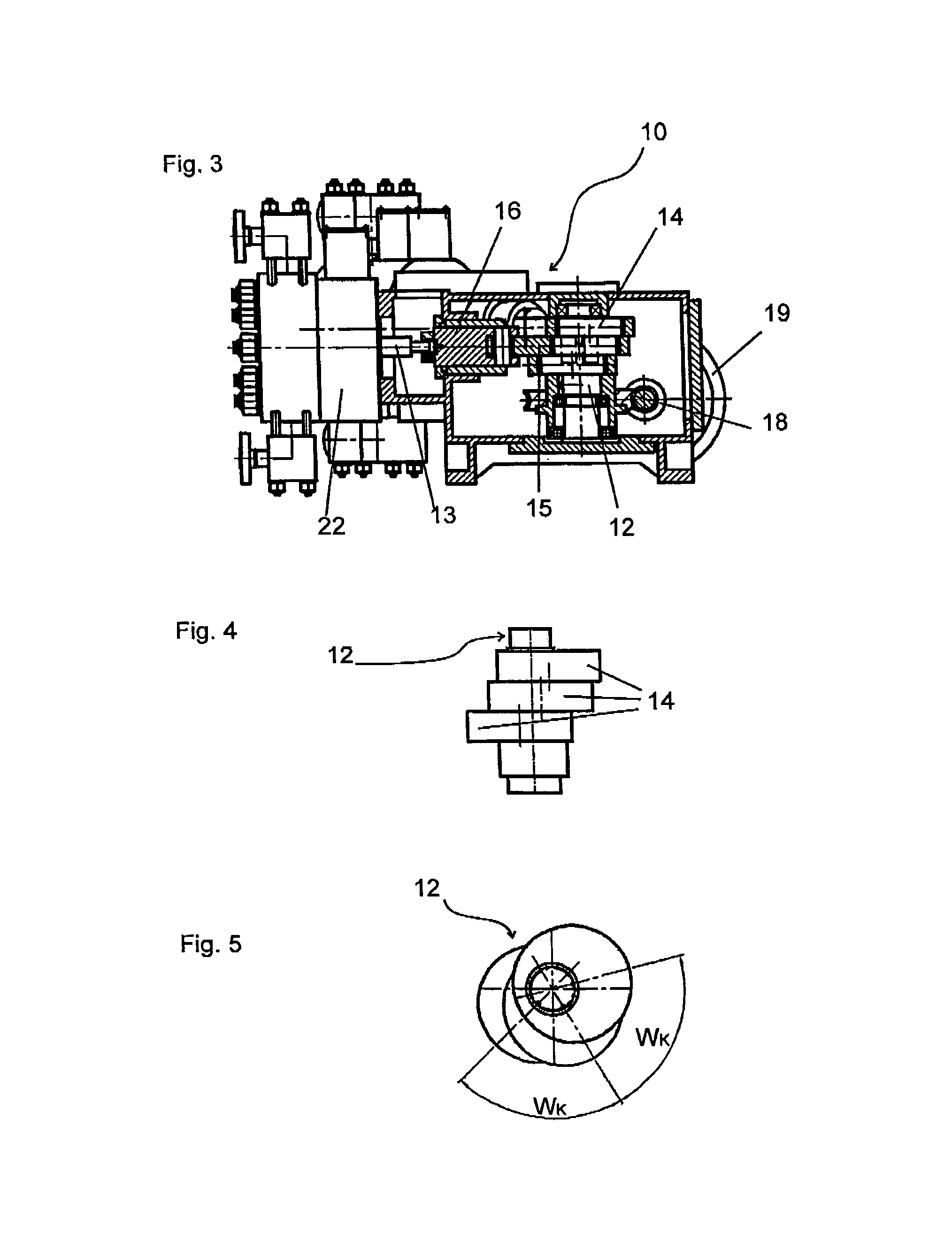
[0038]FIG. 1 shows a possible geometric arrangement of the pump mechanism 10 according to the present invention having three cylinders 11 seen from above. The cylinders 11 point horizontally away radially from the vertically oriented crankshaft 12. They are symmetrically situated in this embodiment and each enclose an angle WZ with one another in the projection shown on a plane perpendicular to the crankshaft 12. A pump mechanism 10 having the same geometry is shown in greater detail in FIG. 2. The sectional plane of the drawing runs through the connecting rod 15 mounted uppermost. The two other connecting rods 15 are mounted without spacing directly below the uppermost connecting rod 15 on the crankshaft 12. The vertical crankshaft 12 is driven via a horizontal worm gear pair 18 using a drive motor 19. The three connecting rods 15 are each mounted on their own crank 14 on the crankshaft 12. On their other end, facing away from the crankshaft 12, they are linked to a crosshead 16. T...


PUM


Abstract

A pump mechanism having multiple cylinders, whose axes are situated around a crankshaft to enclose predetermined angles, and whose pistons are each functionally connected to a connecting rod mounted on a crank on the crankshaft, each connecting rod being mounted on its own crank and the cranks having a predetermined angular offset to one another. This angular offset of the cranks is selected in accordance with the angle which the cylinder axes enclose in such a way that the phase shifts between each two pistons of the cylinders actuated in sequence during a rotation of the crankshaft are equally large.

Description

CROSS-REFERENCE TO RELATED APPLICATIONS[0001]This application claims priority to German Patent Application No. 102005029481.2, filed Jun. 24, 2005, the entire disclosure of which being incorporated herein by reference.FIELD OF THE INVENTION[0002]The present invention relates to a pump mechanism having multiple cylinders, whose axes are situated around a crankshaft to enclose predetermined angles, and whose pistons are each functionally connected to a connecting rod mounted on a crank on the crankshaft.BACKGROUND OF THE INVENTION[0003]Multiple cylinder pump mechanisms are used in process pumps for delivering large delivery streams or at high pressures. Usually, diaphragm pump heads are used as the pump heads in this case. Since the diaphragms used therein are only capable of limited deflection, diaphragm pump heads having very large diameters are required for large delivery volumes. If such large diaphragm pump heads are to be operated using a multiple cylinder mechanism, the interva...

Claims


Application Information

Patent Timeline
Patent Type & Authority Patents(United States)
IPC IPC(8): F04B1/04F04B53/00
CPCF04B1/0413F04B1/0421F04B53/006F04B1/0404F04B1/0408
Inventor PETERSEN, DIRK
Owner BRAN & LUEBBE GMBH
Why Eureka
Try Eureka