
Image coding method and decoding method, image coding apparatus and decoding apparatus, camera, and imaging device

a technology of image coding and decoding methods, applied in the field of image coding methods and decoding methods, image coding apparatus and decoding apparatus, camera, imaging devices, etc., can solve the problems of increasing costs, reduce the information amount of bit change information, reduce quantization errors, and prevent image quality degradation

Active Publication Date: 2015-08-11
PANASONIC SEMICON SOLUTIONS CO LTD
View PDF19 Cites 0 Cited by
  • Summary
  • Abstract
  • Description
  • Claims
  • Application Information

AI Technical Summary

Benefits of technology

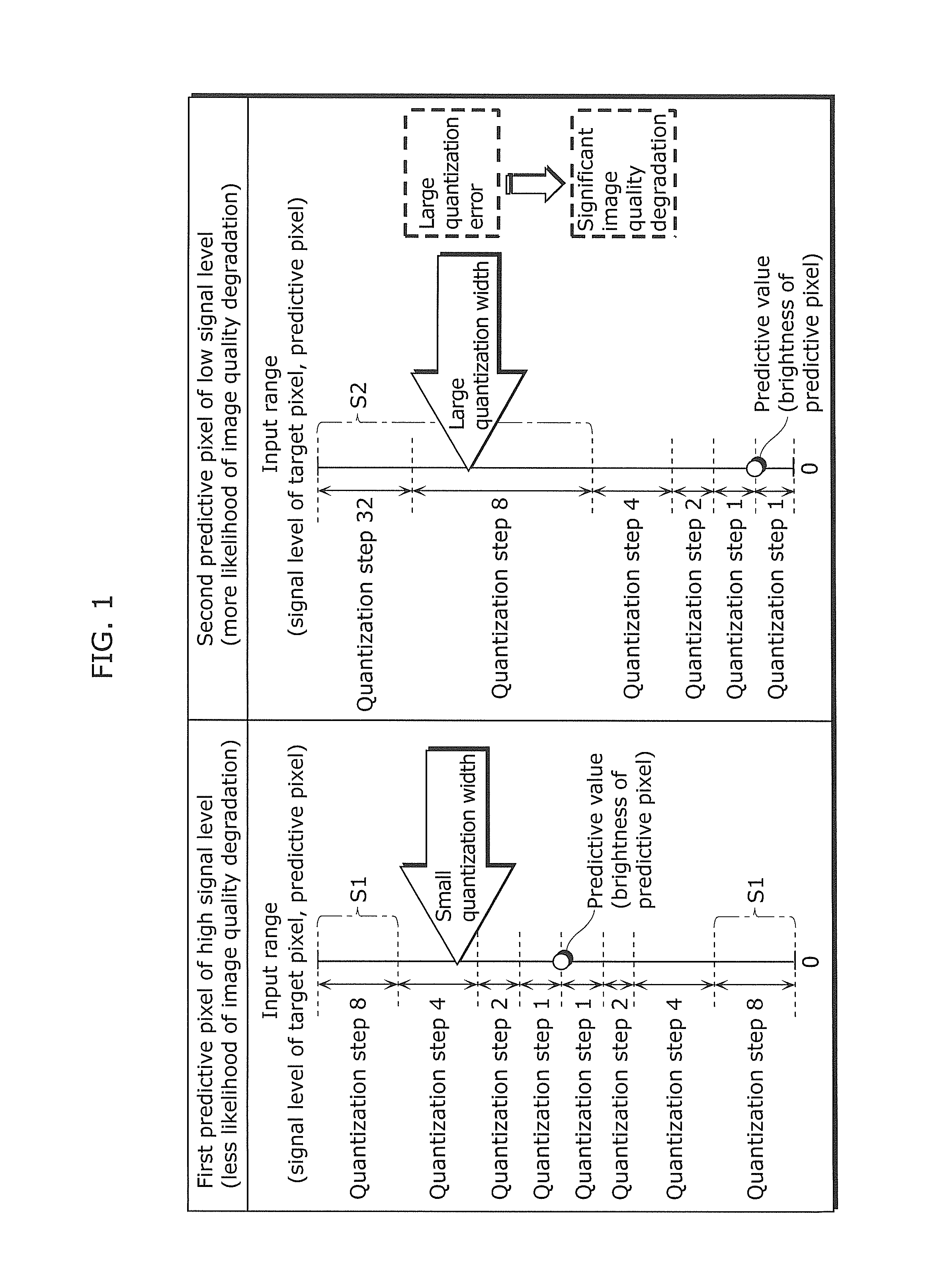
[0034]According to the present invention, sequential processing is performed, so that compression can be carried out with almost no processing delay or need for additional memory. Moreover, since bit change information is quantized unlike conventional difference coding, the number of pixel patterns having an arbitrary quantization width can always be fixed without depending on a signal level of a predictive value. Furthermore, code conversion and bit pattern generation for reducing the information amount of the bit change information enable quantization error reduction.
[0035]By realizing these features by fixed length coding, in the case where a plurality of pieces of fixed length coded data generated as a result are stored in a memory or the like, coded data corresponding to a pixel of a specific part in the image can be easily specified. Thus, random accessibility to coded data can be maintained. That is, according to the present invention, image quality degradation can be prevented as compared with the conventional art, while maintaining random accessibility to a memory.
[0036]Therefore, all of the advantageous effects including sufficiently high image quality, fixed-length quantized (compressed) quantization value generation, and ease of processing can be achieved.

Problems solved by technology

These measures, however, directly result in cost increases.

Method used


Image

  • Image coding method and decoding method, image coding apparatus and decoding apparatus, camera, and imaging device
  • Image coding method and decoding method, image coding apparatus and decoding apparatus, camera, and imaging device
  • Image coding method and decoding method, image coding apparatus and decoding apparatus, camera, and imaging device

Examples


embodiment

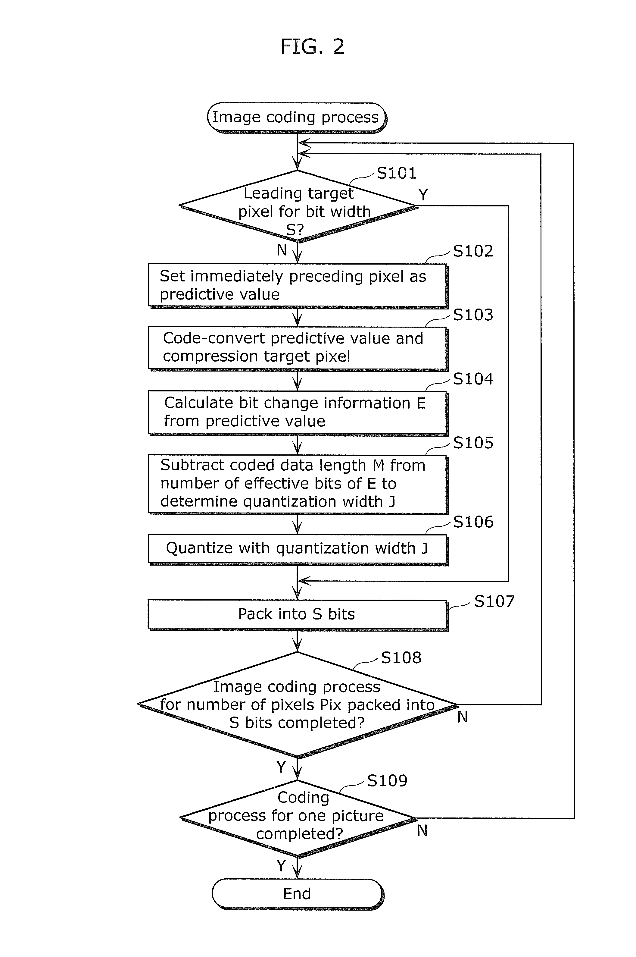
[0132]FIG. 2 is a flowchart showing an image coding method in the embodiment of the present invention.

[0133]FIG. 3 is a block diagram showing structures of an image coding apparatus 100 and an image decoding apparatus 110 in the embodiment of the present invention.

[0134]Note that part or whole of a coding process of the image coding apparatus 100 in this embodiment is implemented by hardware such as LSI (Large Scale Integration) or a program executed by a CPU (Central Processing Unit) or the like. The same applies to each variation of this embodiment.

(Image Coding Process)

[0135]The following describes a process of coding an image (hereafter referred to as an image coding process) by the image coding apparatus 100, with reference to FIGS. 2 and 3.

[0136]A processing target pixel value input unit 101 (FIG. 3) receives a pixel (target pixel) to be coded.

[0137]In this embodiment, it is assumed that each piece of pixel data is digital data of N bits, and quantized pixel data (hereafter re...


PUM


Abstract

An image coding method includes: a predictive pixel generation step of generating a predictive value from at least one surrounding pixel located near a compression target pixel; a code conversion step of code-converting the pixel data to generate a Gray code; and quantizing bit change information (exclusive OR) between the generated Gray code and a Gray code of the predictive value to a quantization value, to compress the pixel data. This prevents significant image quality degradation, so that high image quality can be achieved.

Description

CROSS REFERENCE TO RELATED APPLICATION(S)[0001]This is a continuation application of PCT Patent Application No. PCT / JP2010 / 005441 filed on Sep. 3, 2010, designating the United States of America, which is based on and claims priority of Japanese Patent Applications No. 2009-265670 filed on Nov. 20, 2009 and No. 2010-013659 filed on Jan. 25, 2010. The entire disclosures of the above-identified applications, including the specifications, drawings and claims are incorporated herein by reference in their entirety.TECHNICAL FIELD[0002]The present invention relates to an image coding method and decoding method in an apparatus that handles images, such as a digital still camera, a network camera, or the like. The present invention more specifically relates to an image coding method and decoding method for achieving faster data transfer and less memory usage by image compression, and an apparatus using such image coding method and decoding method.BACKGROUND ART[0003]In recent years, increase...

Claims


Application Information

Patent Timeline
Patent Type & Authority Patents(United States)
IPC IPC(8): H04N7/18H03M7/16H04N19/593H04N19/126H04N19/154H04N19/176H04N19/13H04N19/182H04N19/42H04N19/70H04N19/46G06K9/46H04N1/41H04N19/103H04N19/134H04N19/136H04N19/186H04N19/189H04N19/196H04N19/423H04N19/467H04N19/50H04N19/85
CPCH03M7/16H04N19/176H04N19/13H04N19/593H04N19/126H04N19/154H04N19/182H04N19/70H04N19/46H04N19/42
Inventor OGAWA, MAYUKITAMURA, SHINJIOZAWA, MASAO
Owner PANASONIC SEMICON SOLUTIONS CO LTD
Learn More