Waste heat recovery device
a heat recovery device and waste heat technology, applied in the direction of electric generator control, electric control, machines/engines, etc., can solve the problems of large amount of heat insulator, large space occupied by pipes, and increased pressure loss in pipes, so as to shorten and straighten pipes
- Summary
- Abstract
- Description
- Claims
- Application Information
AI Technical Summary
Benefits of technology
Problems solved by technology
Method used
Image
Examples
embodiment 1
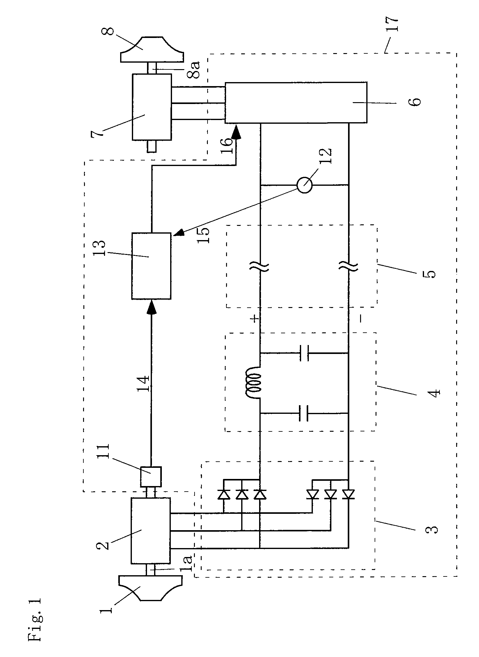
[0039]FIG. 1 is a view of Embodiment 1 in the present invention.
[0040]In this drawing, 1 is a turbine, la is a shaft, 2 is a generator, 3 is a rectifier, 4 is a smoothing circuit, 5 is a direct current bus, 6 is an inverter, 7 is an electric motor, 8 is a compressor, 8a is a shaft, 11 is a rotation speed detector, 12 is a voltage detector, 13 is a rotation speed command unit, 14 is a rotation speed, 15 is a voltage, 16 is a rotation speed command value, and 17 is a control device.
[0041]The generator 2 is directly connected to the turbine 1 rotated by an exhaust gas from a heat engine (not shown) via the shaft la. Moreover, the generator 2 rotates integrally with the turbine 1 to generate electric power.
[0042]For example, a permanent magnet synchronous motor driven by a three-phase alternate current can be used as the generator 2.
[0043]The control device 17 drives the electric motor 7 by using the electric power generated by the generator 2 as a power source. Moreover, the control de...
embodiment 2
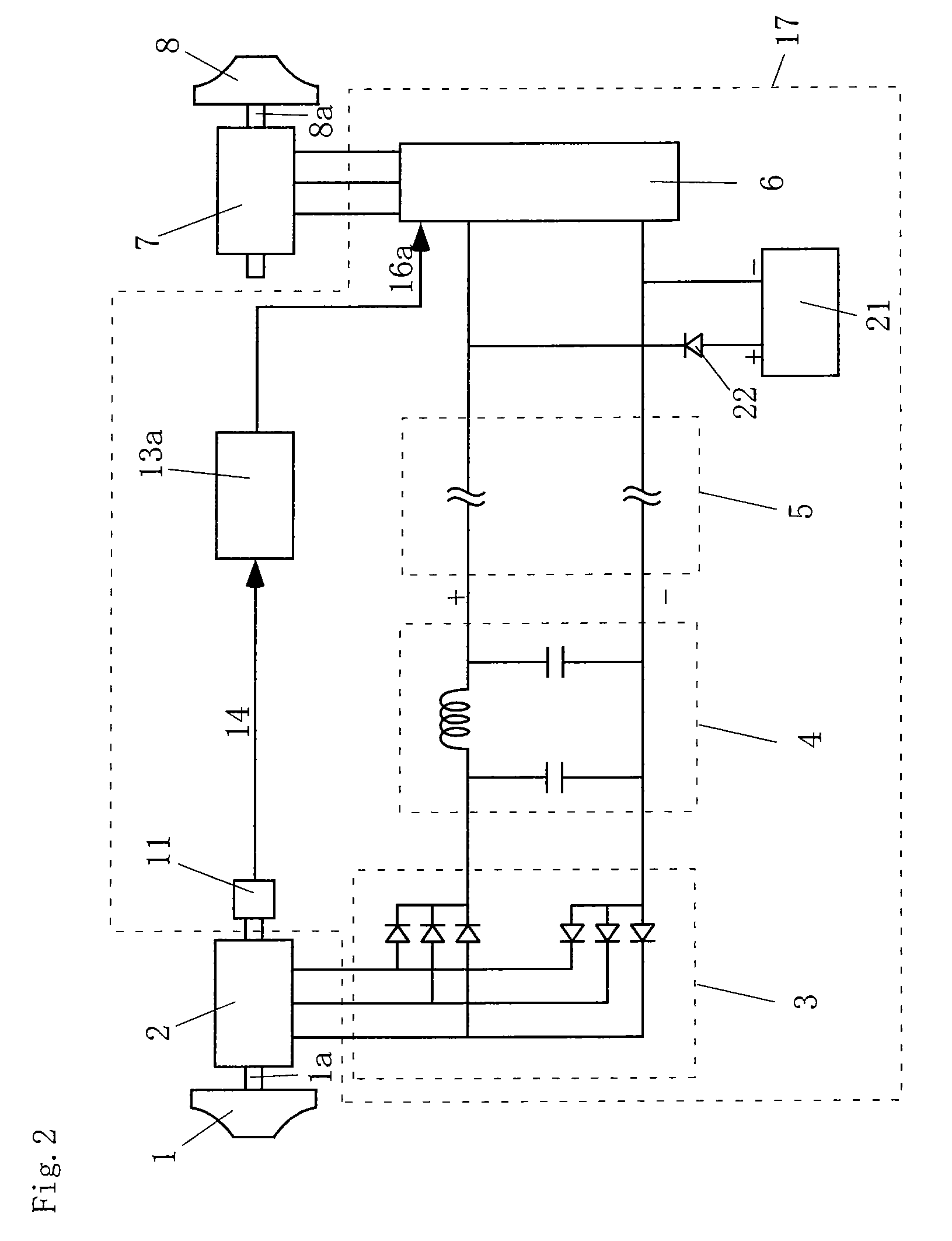
[0070]FIG. 2 is a view of a turbo charger of Embodiment 2 in the present invention.
[0071]In this drawing, 13a is a rotation speed command unit, 16a is a rotation speed command value, 21 is a direct current power source, and 22 is a diode. The same constituent elements as those of Embodiment 1 are denoted with the same reference signs as in FIG. 1, and description is omitted.
[0072]A control device 17 drives an electric motor 7 by using electric power generated by a generator 2 as a power source. Moreover, the control device 17 of the present embodiment includes a rectifier 3, a smoothing circuit 4, a direct current bus 5, an inverter 6, a rotation speed detector 11, the rotation speed command unit 13a, the direct current power source 21, and the diode 22.
[0073]The rotation speed command unit 13a outputs, to the inverter 6, the rotation speed command value 16a of the electric motor 7 and a compressor 8 based on rotation speed 14 of a turbine 1 and the generator 2 which is detected by ...
embodiment 3
[0085]FIG. 3 is a view of a turbo charger of Embodiment 3 in the present invention.
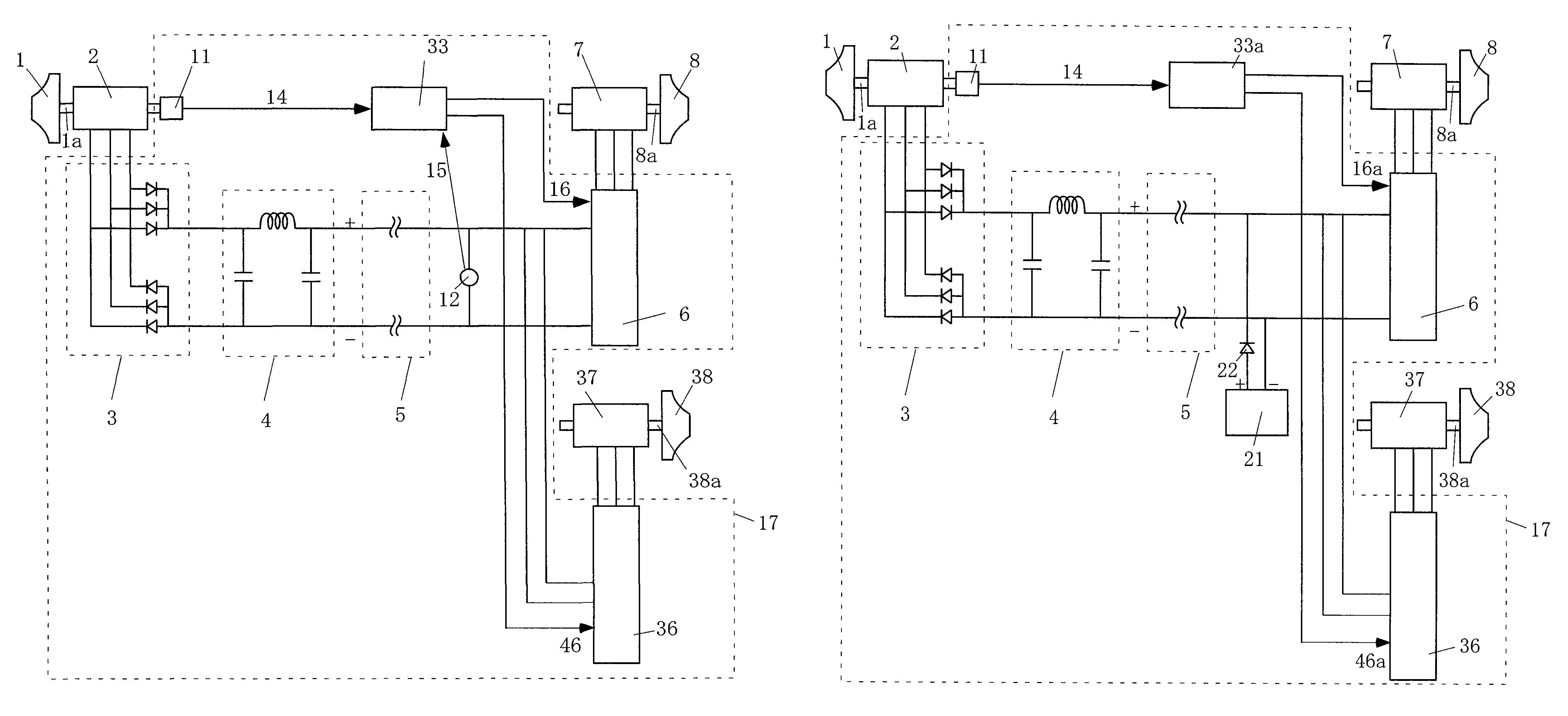
[0086]In this drawing, 33 is a rotation speed command unit, 36 is an inverter, 37 is an electric motor, 38 is a compressor, and 38a is a shaft. The same constituent elements as those of Embodiment 1 are denoted with the same reference signs as in FIG. 1, and description is omitted.
[0087]A control device 17 drives electric motors 7 and 37 by using electric power generated by a generator 2 as a power source. Moreover, the control device 17 of the present embodiment includes a rectifier 3, a smoothing circuit 4, a direct current bus 5, inverters 6 and 36, a rotation speed detector 11, a voltage detector 12, and the rotation speed command unit 33.
[0088]The rotation speed command unit 33 outputs, to the inverters, rotation speed command values of the electric motors and the compressors for each of a plurality of sets of the electric motors, the compressors and the inverters, based on rotation speed 14 of a...
PUM
 Abstract
Description
Claims
Application Information
 - R&D
- Intellectual Property
- Life Sciences
- Materials
- Tech Scout
- Unparalleled Data Quality
- Higher Quality Content
- 60% Fewer Hallucinations
Browse by: Latest US Patents, China's latest patents, Technical Efficacy Thesaurus, Application Domain, Technology Topic, Popular Technical Reports.
© 2025 PatSnap. All rights reserved.Legal|Privacy policy|Modern Slavery Act Transparency Statement|Sitemap|About US| Contact US: help@patsnap.com


