Methods and systems for condensation control

a condensation control and condensation technology, applied in the direction of electric control, machines/engines, mechanical equipment, etc., can solve the problems of condensation build-up at the cac, the coolant temperature in the engine cooling circuit may not be high enough to transfer sufficient heat to the cac cooling circuit, and the misfire and nvh problems, so as to improve the peak power output, increase the charge density, and increase the fuel economy

Active Publication Date: 2015-08-18
FORD GLOBAL TECH LLC
View PDF43 Cites 43 Cited by
  • Summary
  • Abstract
  • Description
  • Claims
  • Application Information

AI Technical Summary

Benefits of technology

[0002]Engine systems may be configured with boosting devices, such as turbochargers or superchargers, for providing a boosted aircharge and improving peak power outputs. The use of a compressor allows a smaller displacement engine to provide as much power as a larger displacement engine, but with additional fuel economy benefits. A charge air cooler (CAC) may be provided downstream of the compressor for cooling the boosted aircharge, thereby increasing the charge density, before it is delivered to the engine intake. As such, the charge air cooler may be coupled to a coolant loop that is distinct from, and not connected to, the engine coolant loop used to heat / cool the engine. Due to this separation, the charge air cooler may run at cooler temperatures (e.g., ambient temperatures) for extended durations. When EGR is introduced upstream of the charge air cooler, condensation can occur. When ingested, the condensate can cause misfires and NVH issues.
[0003]One approach to intermittently warm the CAC is taught by Vigild et al. in US 2012 / 0297765. Therein, the charge air cooler is fluidly connected to each of the engine cooling circuit and the CAC cooling circuit via a plurality of valve devices. By opening a first valve during a first set of conditions, the CAC cooling circuit is exposed to hotter coolant from the engine cooling circuit, enabling a periodic raising of the temperature of the CAC cooling circuit. In comparison, by opening a second valve during a second set of conditions, the CAC cooling circuit is exposed to cooler coolant from the CAC cooling circuit, enabling a lower temperature of the CAC cooling circuit to be maintained.
[0005]Thus in one example, the above issues may be at least partly addressed by a method for a boosted engine comprising: closing a wastegate and an EGR valve while opening a compressor recirculation valve to heat a charge air cooler coupled downstream of a compressor responsive to cold conditions. In this way, transferring of turbine energy to the intake air may be used to warm the intake aircharge and increased compressor recirculation flow of the heated aircharge can be used to warm the charge air cooler.
[0006]For example, an engine system may include an intake compressor with a compressor bypass coupling an outlet of a downstream charge air cooler (CAC) to an inlet of the compressor. By adjusting the position of a compressor recirculation valve (CRV) in the compressor bypass, an amount of (cooled) compressed air may be recirculated from downstream of the CAC to the compressor inlet. The CAC may be coupled to a cooling circuit. The engine system may further include an exhaust turbine for driving the compressor, with a wastegate coupled in a bypass across the turbine. During cold conditions, such as when the CAC has been below a threshold temperature for an extended period of time, during an engine cold-start, or when ambient conditions are cold, an engine controller may actively close the wastegate to increase the exhaust pressure and spin the turbine. By recovering exhaust energy via the turbine and transferring energy to the intake air, the temperature of the CAC and the incoming intake air is increased. By simultaneously opening the CRV, the heated aircharge can be recirculated around the compressor and the CAC, thereby expediting warming the CAC. In addition, by increasing the recirculation of heated air across the CAC (via the CRV), heat transfer to the CAC (and the CAC cooling circuit) is increased without incurring a substantial increase in throttle inlet pressure.
[0007]An EGR valve may be maintained closed while the wastegate is closed and the CRV is opened so that the delivery of EGR is delayed until the CAC is sufficiently warm. Once the CAC temperature is above a threshold temperature, the EGR valve may be opened. By introducing EGR only after the CAC is sufficiently warm, the propensity for condensation and the associated issues are reduced. Increased delivery of low pressure EGR following warming of the CAC can be used to expedite engine heating. Specifically, as EGR is introduced, heat may be rejected by an EGR cooler to the engine cooling circuit to thereby warm up the engine.
[0008]In this way, exhaust heat may be recovered via a wastegate and added to a CAC during cold conditions to expedite warming of the CAC during cold engine conditions. By expediting warming of the CAC, EGR benefits can be achieved during low ambient conditions. By increasing the window for EGR operation without condensation, the overall fuel economy can be improved. By delaying introduction of EGR to a compressor inlet until the CAC has been warmed, EGR condensation is reduced. As such, this reduces the occurrence of misfires and other condensate ingestion related NVH issues.

Problems solved by technology

When ingested, the condensate can cause misfires and NVH issues.
However the inventors herein have identified potential issues with such an approach.
As one example, during cold start conditions, coolant temperatures in the engine cooling circuit may not be high enough to transfer sufficient heat to the CAC cooling circuit.
During such conditions, the introduction of any EGR can lead to condensation build up at the CAC.
While the CAC can be warmed using engine heat, it requires prior engine warm-up which can be slow during an engine cold-start.
In addition, the approach of '765 requires the use of additional components, such as valves and fluid passages, which may increase cost and complexity of the system.
Further still, turning off the cooling circuit pump limits heat transfer to the ambient.

Method used


Image

  • Methods and systems for condensation control
  • Methods and systems for condensation control
  • Methods and systems for condensation control

Examples


Embodiment Construction

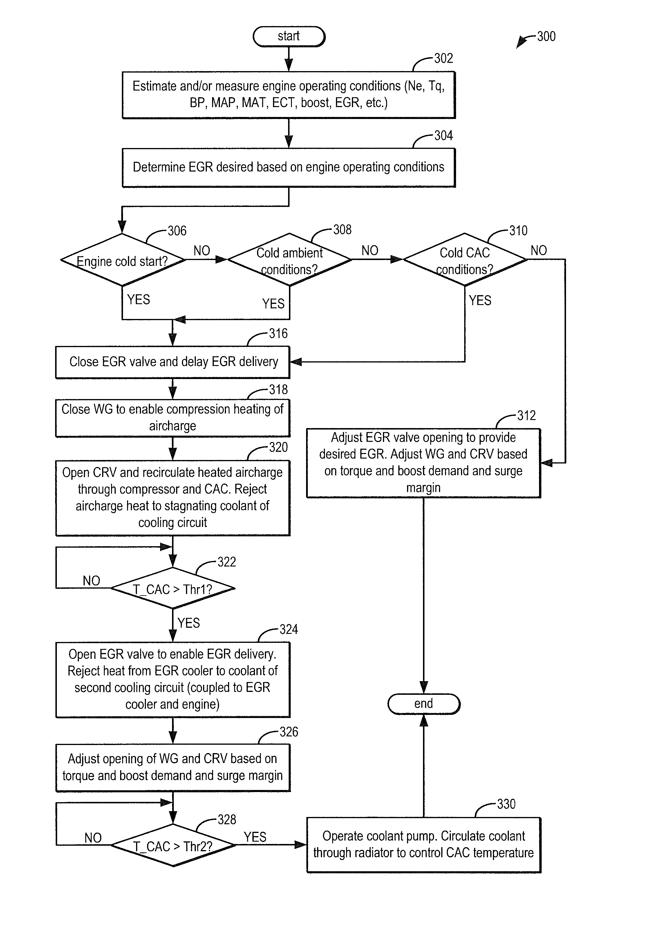
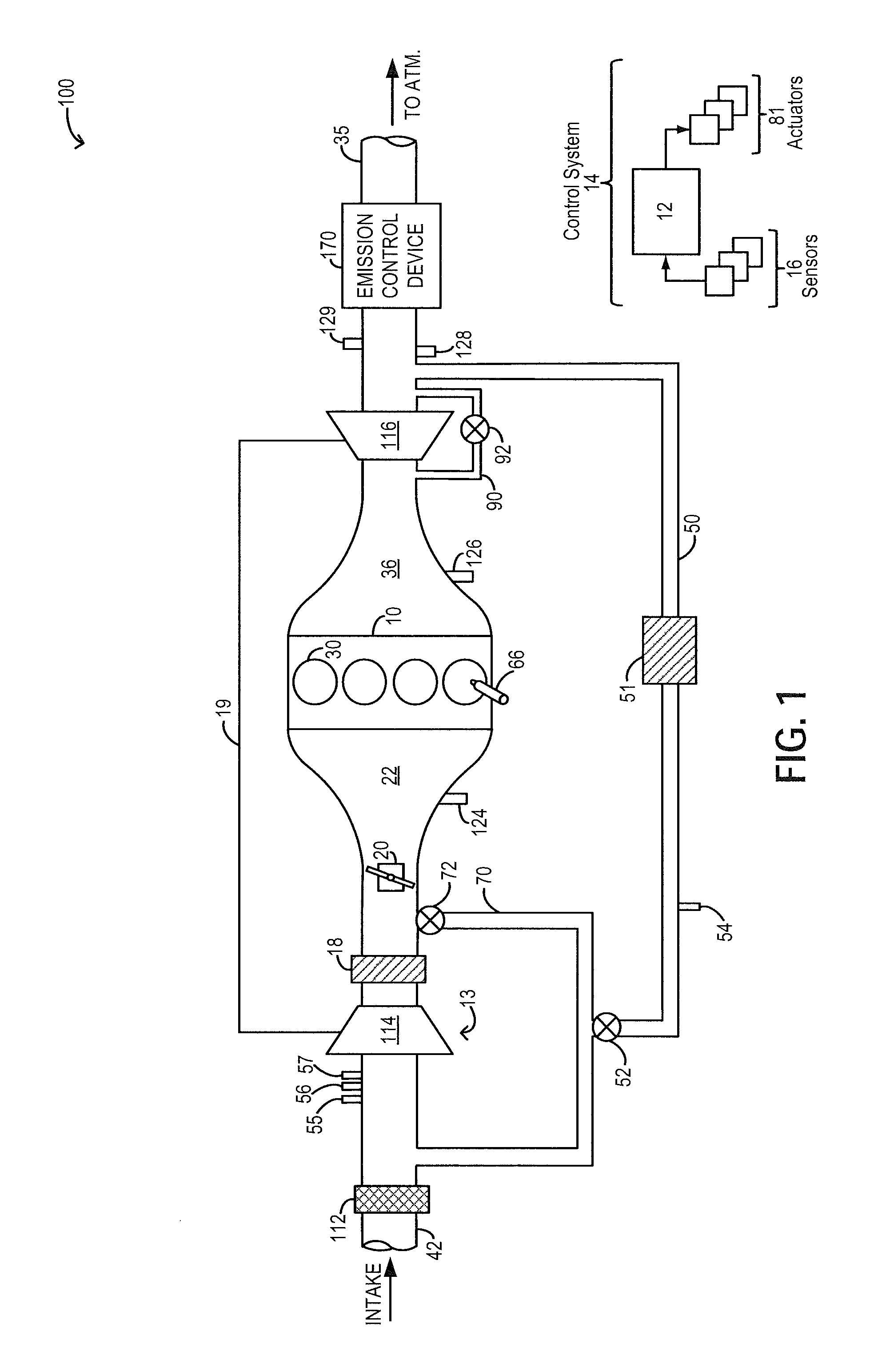
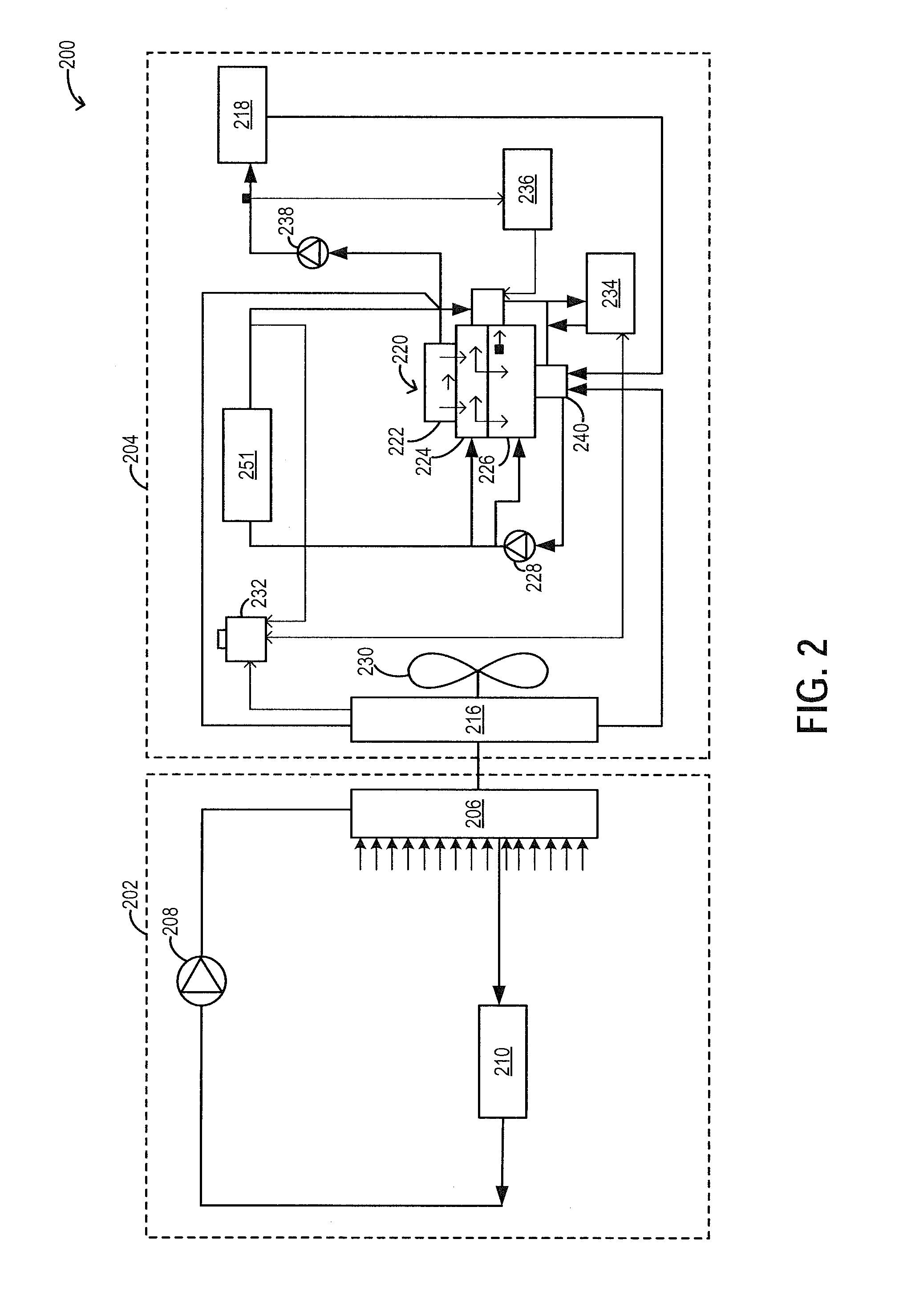
[0014]Methods and systems are provided for recovering exhaust heat from an engine system, such as the engine system of FIG. 1, to warm charge flowing through a charge air cooler (CAC). In doing so, intake aircharge and coolant flowing though the charge air cooler's cooling circuit (such as the circuit of FIG. 2), can be warmed. An engine controller may be configured to perform a control routine, such as the routine of FIG. 3, to recover exhaust heat by closing a wastegate during cold conditions to increase exhaust pressure and temperature upstream of a turbine. By raising the backpressure, work is extracted from the exhaust blow-down energy. Thus turbine power is transferred to the intake air via the compressor. By concurrently opening a compressor recirculation valve, the heated charge can be recirculated across the CAC, thereby warming the CAC cooling circuit. EGR delivery may be initiated once the CAC has been sufficiently warmed. An example adjustment is shown with reference to ...


PUM


Abstract

Methods and systems are provided for reducing condensate accumulation at a charge air cooler (CAC) during cold ambient conditions. A wastegate may be held closed while a compressor recirculation valve is held open during an engine cold start so as to use compressor heating and increased compressor recirculation to expedite CAC heating. EGR delivery is delayed until the CAC is sufficiently warm to reduce the propensity for condensation.

Description

FIELD[0001]The present application relates to methods and systems for using compressive heating of intake air to speed warming of a charge air cooler.BACKGROUND AND SUMMARY[0002]Engine systems may be configured with boosting devices, such as turbochargers or superchargers, for providing a boosted aircharge and improving peak power outputs. The use of a compressor allows a smaller displacement engine to provide as much power as a larger displacement engine, but with additional fuel economy benefits. A charge air cooler (CAC) may be provided downstream of the compressor for cooling the boosted aircharge, thereby increasing the charge density, before it is delivered to the engine intake. As such, the charge air cooler may be coupled to a coolant loop that is distinct from, and not connected to, the engine coolant loop used to heat / cool the engine. Due to this separation, the charge air cooler may run at cooler temperatures (e.g., ambient temperatures) for extended durations. When EGR i...

Claims


Application Information

Patent Timeline
Patent Type & Authority Patents(United States)
IPC IPC(8): F02D23/00F02B47/08F02M25/07F02D41/00
CPCF02B47/08F02D41/0047F02M25/07F02M25/071F02M25/0709F02M25/0727F02D41/064F02D41/068F02D41/0007F02D41/0055F02D2200/0414F02M26/07F02M26/06F02M26/23Y02T10/12Y02T10/40
Inventor ULREY, JOSEPH NORMANBUCKLAND, JULIA HELEN
Owner FORD GLOBAL TECH LLC
Why Eureka
Try Eureka