
Contactless rotary joint with safety function

a rotary joint and safety function technology, applied in radiation safety means, applications, tomography, etc., can solve problems such as personal injury or damage, and achieve the effects of simple and reliable signaling, high security and protection of the operating person, and simple and cost-effectiv

Active Publication Date: 2015-08-18
SCHLEIFRING & APPBAU
View PDF10 Cites 1 Cited by
  • Summary
  • Abstract
  • Description
  • Claims
  • Application Information

AI Technical Summary

Benefits of technology

The patent aims to provide a simple and cost-efficient solution for switching loads on a rotating part of a machine. The system uses a rotary joint and a main power switch to transfer power from a stationary part. This setup ensures high security and protection for operating personnel. The second input circuit is connected to an external three-phase line, which is connected to a main power switch. This enables the control unit on the secondary side to activate the load using the higher voltage generated by the input circuit. The system is immune to electromagnetic interference and can detect and isolate any faults in the components. The technical effect of the invention is to provide a reliable and efficient solution for switching loads on a rotating machine.

Problems solved by technology

Unwanted enabling (activation) of the load may lead to personal injury or damage.

Method used


Image

  • Contactless rotary joint with safety function
  • Contactless rotary joint with safety function

Examples


Embodiment Construction

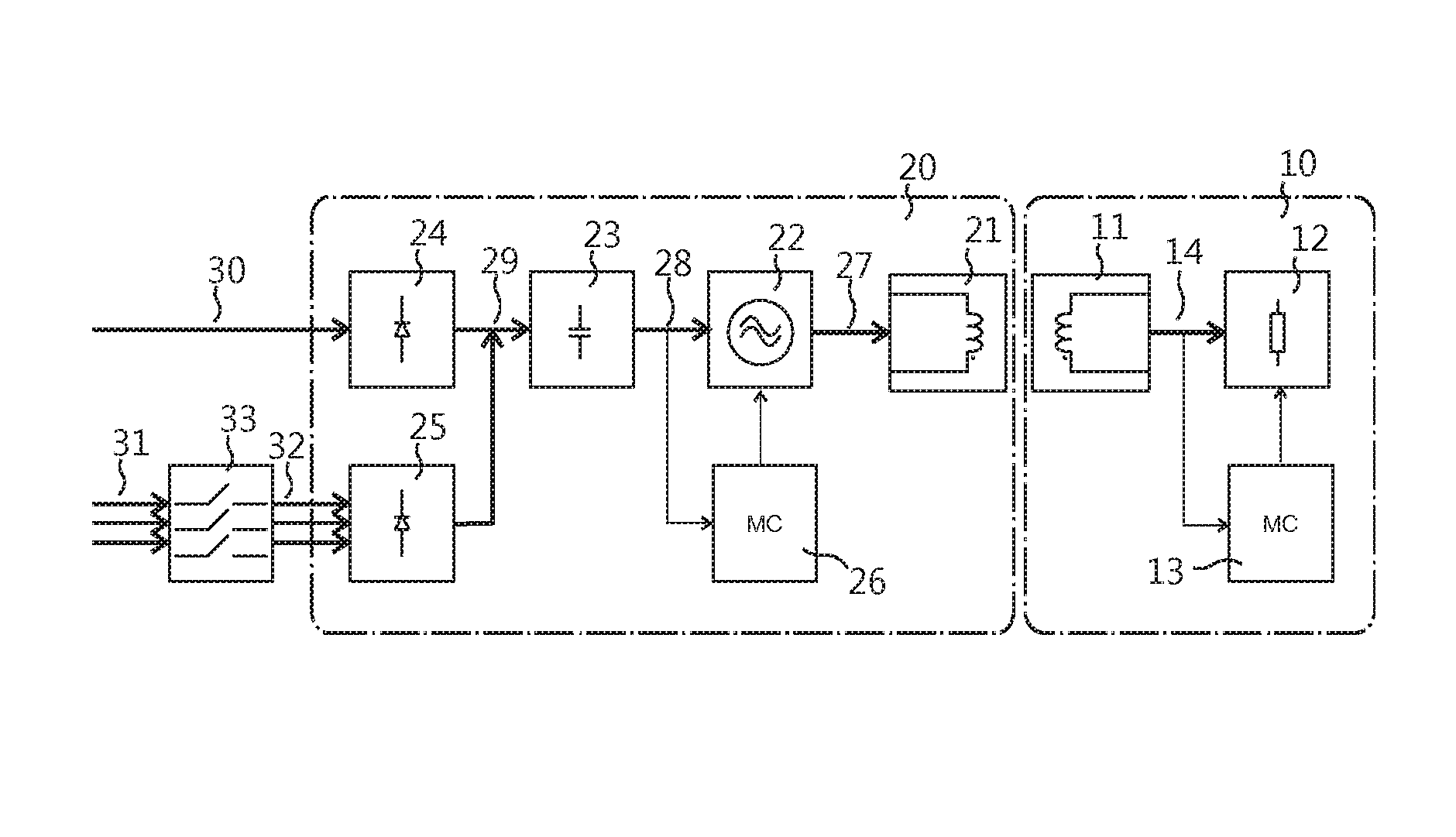
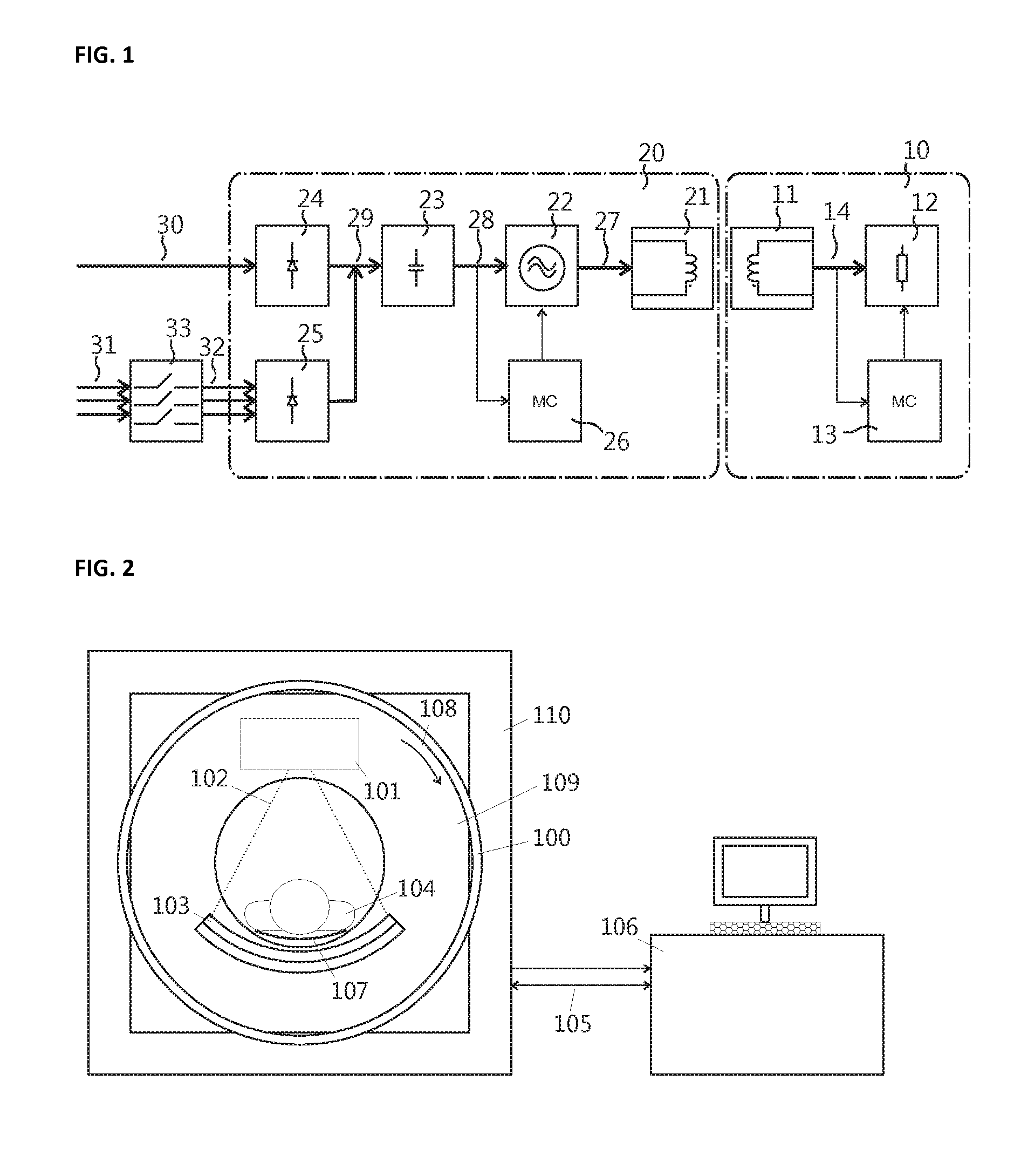
[0029]In FIG. 1 a preferred embodiment is shown. On the stationary part 20 an inductive rotary joint system has a first input circuit as a one phase rectifier 24 for receiving a one phase AC input 30, generating a comparatively lower DC voltage at the output of the one phase rectifier. Furthermore a second input circuit as a three phase rectifier 25 is provided for receiving a three phase input 32 connected by a main power switch 33 to an external three phase AC line 31, generating a comparatively higher DC voltage and output of the three-phase rectifier. This main power switch 33 may also be a part of the second input circuit. The tree phase input is preferably connected by a main power switch 33, preferably an x-ray main switch to an external three phase AC power line. The DC voltage (29) generated by the rectifiers is filtered by a filtering circuit 23. An AC power generator 22 generates an AC signal 27 from the DC voltage, which is coupled by an inductive rotary joint 21, 11 to ...


PUM


Abstract

Inductive rotary joint system with stationary and rotating sides has a one-phase rectifier for receiving one-phase AC-input to generate low-level DC-voltage, and a three-phase rectifier for receiving three-phase input to generate higher-level DC-voltage. An AC-power generator receives DC-voltage and generates AC-power, which is coupled by an inductive rotary joint to a load at the rotating side. Voltage coupled to the load is comparably higher when the one-phase rectifier is connected and comparably lower when the three-phase rectified is connected. A control unit at the secondary side for controlling at least the load is connected to measure the voltage produced for the secondary side, and to distinguish between a comparatively lower voltage and a comparatively higher voltage. When a presence of a comparatively higher voltage is indicated, an x-ray tube is enabled within the load.

Description

PRIORITY CLAIM[0001]This application claims priority to pending European Application No. 11172372.2 filed on 1 Jul. 2011 and abandoned European Application No. 11168041.9 filed on 30 May 2011.BACKGROUND OF THE INVENTION[0002]1. Field of the Invention[0003]The invention relates to an inductive power coupling device for coupling electrical power between two units being rotatable against each other, specifically for power couplers used in computer tomography scanners. Such power couplers are also known as rotary joints.[0004]2. Description of Relevant Art[0005]In computer tomography scanners and other related machines high-power in the range of 10 kW up to more than 100 kW is transferred from the stationary the rotating side. There a high voltage in the range of above hundred kilovolts is generated to produce x-ray radiation. The high voltage and the x-ray radiation may cause physical damage to operating personal under specific conditions like during service when protective covers are ...

Claims


Application Information

Patent Timeline
Patent Type & Authority Patents(United States)
IPC IPC(8): H02J5/00A61B6/00A61B6/03A61B6/10
CPCH02J5/005A61B6/56A61B6/032A61B6/10H02J50/12H02J2310/23
Inventor KRUMME, NILS
Owner SCHLEIFRING & APPBAU
Learn More