Internal backbone structural chassis for a surgical device

a surgical device and chassis technology, applied in the field of power head removal and battery compartment, can solve the problems of contaminated medical waste, higher precision, and complex components, and achieve the effect of reducing contaminated medical was

Active Publication Date: 2015-08-25
TYCO HEALTHCARE GRP LP
View PDF42 Cites 1398 Cited by
  • Summary
  • Abstract
  • Description
  • Claims
  • Application Information

AI Technical Summary

Benefits of technology

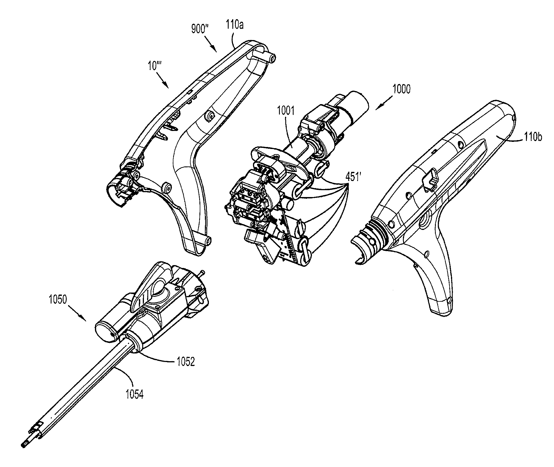
[0009]To advance the state of the art with respect to reducing contaminated medical waste, the present disclosure relates to a chassis for mounting a set of operating components of a power head of a surgical instrument. The power head has a housing enabling access to an interior volume of the power head encompassed by the housing. The set of operating components have a proper configuration for alignment when mounted within the interior volume encompassed by the housing. The chassis is configured to provide the proper configuration for alignment for either the set of operating components mounted on the chassis if the chassis and set of operating components are mounted within the interior volume of the housing and a replacement set of operating components of the power head mounted on the chassis if the chassis and replacement set of operating components are mounted within the interior volume of the housing. In one embodiment, the chassis is formed from metal and the housing is formed from a polymer.

Problems solved by technology

Contact or exposure to contamination from the external surface of a used surgical device, gloves or garments will classify the battery pack as hazardous medical waste.
These components may require rare materials or intensive processing methods.
Additionally the components are generally more complex, higher precision and require tighter tolerance constraints to produce.
These higher cost parts may also lead the designs towards greater reusability.
These components are limited to certain materials, shapes and processes which in turn limits accuracy and strength.
When a housing of a surgical instrument power head becomes contaminated, reusability or reprocessing of costly internal components often is impeded because of the difficulty of removing the internal components from the contaminated housing without also contaminating the internal components.

Method used


Image

  • Internal backbone structural chassis for a surgical device
  • Internal backbone structural chassis for a surgical device
  • Internal backbone structural chassis for a surgical device

Examples


Embodiment Construction

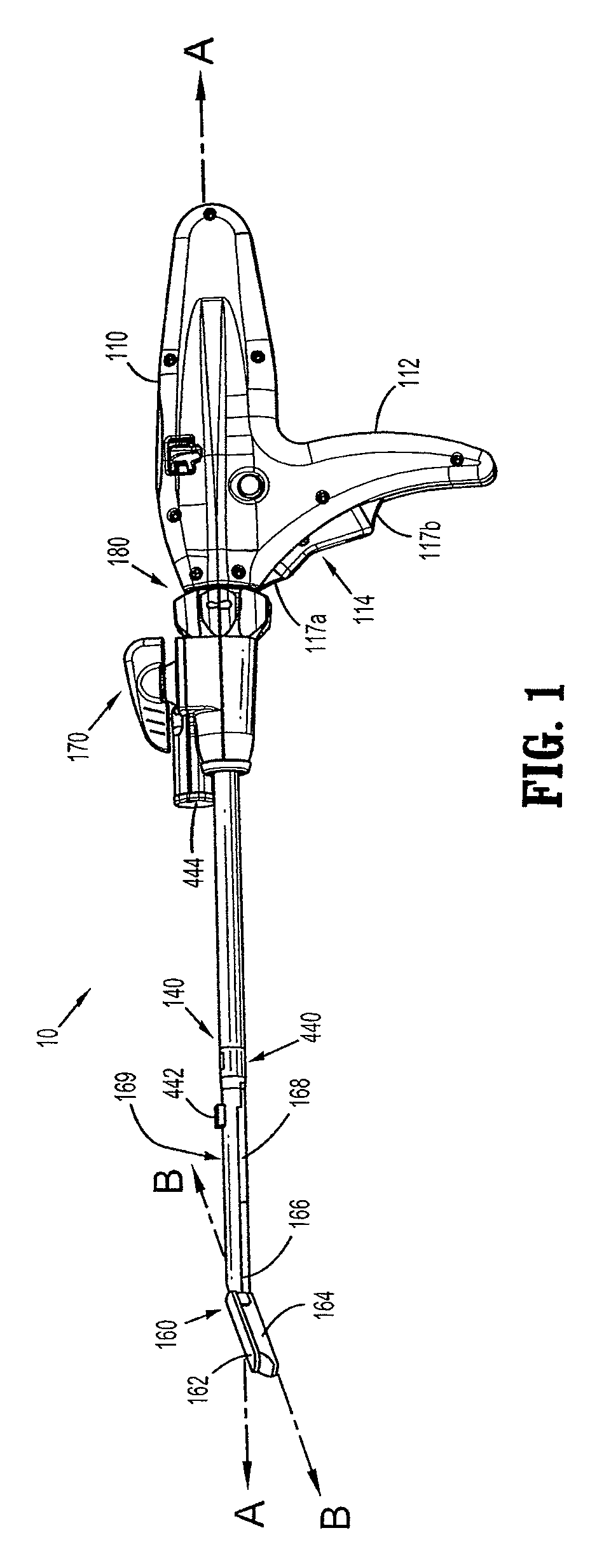
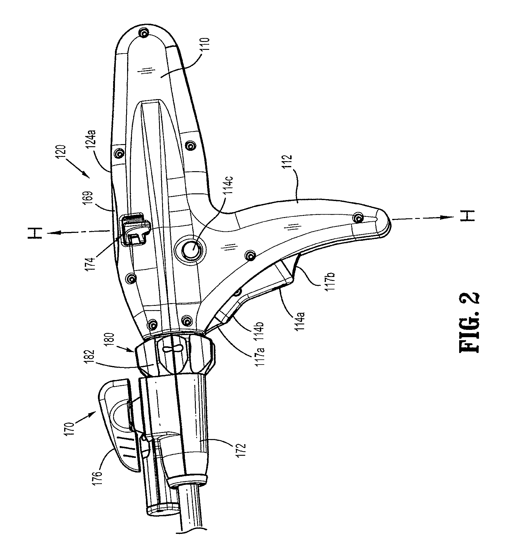
[0058]Embodiments of the presently disclosed powered surgical instrument are now described in detail with reference to the drawings, in which like reference numerals designate identical or corresponding elements in each of the several views. As used herein the term “distal” refers to that portion of the powered surgical instrument, or component thereof, farther from the user while the term “proximal” refers to that portion of the powered surgical instrument or component thereof, closer to the user.

[0059]Additionally, in the drawings and in the description that follows, terms such as “front”, “rear”, “upper”, “lower”, “top”, “bottom” and the like are used simply for convenience of description and are not intended to limit the disclosure thereto.

[0060]A powered surgical instrument, e.g., a surgical stapler, in accordance with the present disclosure is referred to in the figures as reference numeral 10. Referring initially to FIG. 1, powered surgical instrument 10 includes a housing 11...


PUM

PropertyMeasurementUnit
period of timeaaaaaaaaaa
frequencyaaaaaaaaaa
frequencyaaaaaaaaaa

Abstract

A chassis for mounting a set of operating components of a power head of a surgical instrument is disclosed. The power head has a housing enabling access to an interior volume of the power head encompassed by the housing. The set of operating components have a proper configuration for alignment when mounted within the interior volume encompassed by the housing. The chassis is configured to provide the proper configuration for alignment of either an original or replacement set of operating components mounted on the chassis if the chassis and set of operating components are mounted within the interior volume of the housing. The chassis may be formed from metal and the housing formed from a polymer. The chassis may be configured to ground at least one electrical component.

Description

CROSS-REFERENCE TO RELATED APPLICATIONS[0001]This application claims priority to U.S. Provisional Patent Application No. 61 / 248,971 by Zemlok et al., entitled “INTERNAL BACKBONE STRUCTURAL CHASSIS FOR A SURGICAL DEVICE”, filed on Oct. 6, 2009 and to U.S. Provisional Patent Application No. 61 / 248,504 by Zemlok et al., entitled “BATTERY EJECTION DESIGN FOR A SURGICAL DEVICE”, filed on Oct. 5, 2009. This application is a continuation-in-part of U.S. patent application Ser. No. 12 / 189,834 by Zemlok et al., entitled “POWERED SURGICAL STAPLING DEVICE”, filed on Aug. 8, 2008, published as U.S. Patent Application Publication No. US 2009 / 0090763 A1, which claims priority to U.S. Provisional Patent Application No. 60 / 997,854 by Zemlok et al., entitled “POWERED SURGICAL STAPLING DEVICE”, filed on Oct. 5, 2007, the entire contents of each of which are hereby incorporated by reference herein.BACKGROUND[0002]1. Technical Field[0003]This application relates to a power head for a surgical apparatus...

Claims


Application Information

Patent Timeline
Patent Type & Authority Patents(United States)
IPC IPC(8): A61B17/072A61B17/32A61B17/00A61B17/29A61B19/00
CPCA61B17/07207A61B19/5225A61B2017/00017A61B2017/00022A61B2017/00084A61B2017/00367A61B2017/00398A61B2017/00464A61B2017/00473A61B2017/00477A61B2017/00482A61B2017/00734A61B2017/2927A61B2017/2931A61B2017/320052A61B90/37
Inventor ZEMLOK, MICHAEL A.MARCZYK, STANISLAWROSS, ADAM J.
Owner TYCO HEALTHCARE GRP LP
Why Eureka
Try Eureka