A sterile dispensing system

A dispensing system and dispensing technology, applied in medical containers, drug packaging, packaged food, etc., can solve the problems of increased drug contamination, high labor intensity, and difficult operation, so as to avoid medical accidents, reduce labor intensity, and protect the environment Effect

Active Publication Date: 2018-12-07
哈尔滨碧研科技有限公司
View PDF8 Cites 0 Cited by
  • Summary
  • Abstract
  • Description
  • Claims
  • Application Information

AI Technical Summary

Problems solved by technology

In this process, nurses continuously operate the dispensing device to absorb and inject liquid, which is labor-intensive, low in efficiency, and prone to errors in manual operation
Moreover, the traditional dispensing device is exposed to the air for a long time, so that the dispensing push rod of the dispensing device is easily polluted during the dispensing operation. If bacteria are brought into the dispensing device, it is easy to cause contamination of the medicine; on the other hand , When dispensing medicine, nurses are required not to touch the dispensing pusher of the dispensing device with their hands. The operation is difficult and mistakes are inevitable, which increases the risk of drug contamination

Method used


Image

  • A sterile dispensing system
  • A sterile dispensing system
  • A sterile dispensing system

Examples


Embodiment 1

[0047] Different from the aseptic dispensing system described above, this embodiment is different in that one end of the front push rod 41 is provided with an external thread, and the tail end of the rubber plug 2 is provided with a The internal thread joint corresponding to the external thread; through the front push rod 41 rotating around the axis while advancing, the external thread of the front push rod 41 is screwed with the internal thread joint of the rubber plug 2, so that the The front push rod 41 is combined with the rubber plug 2 .

Embodiment 2

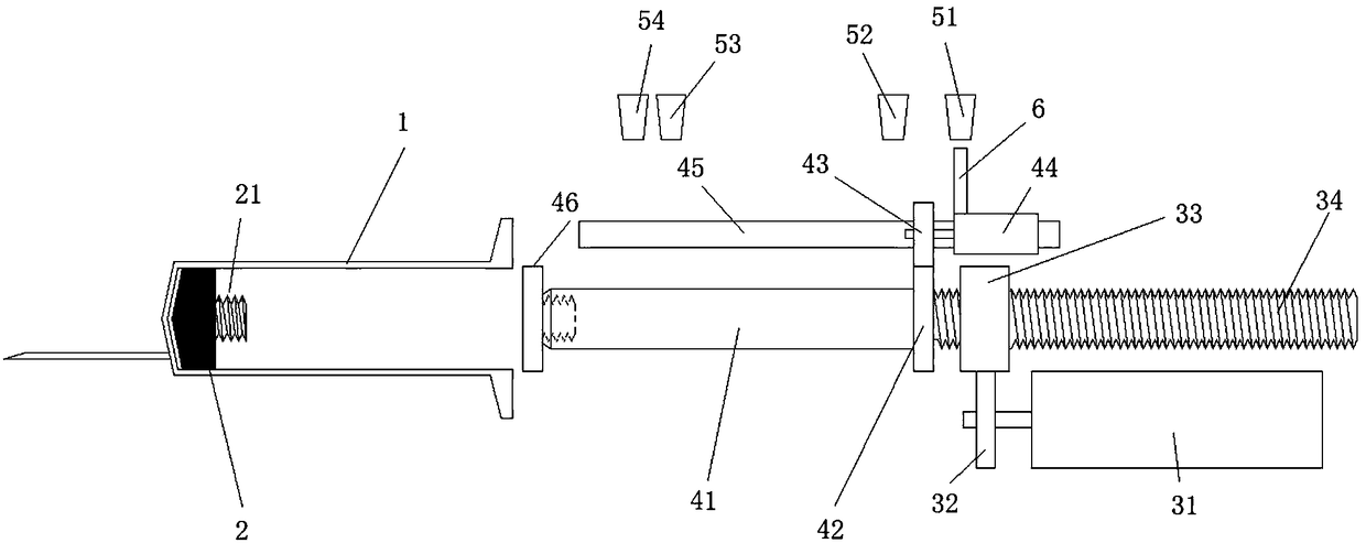
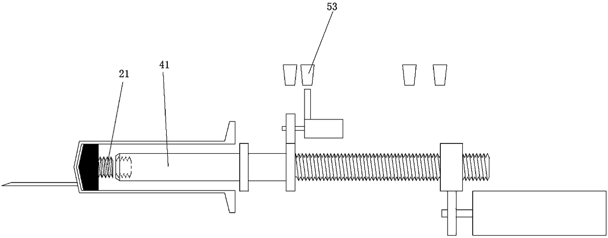
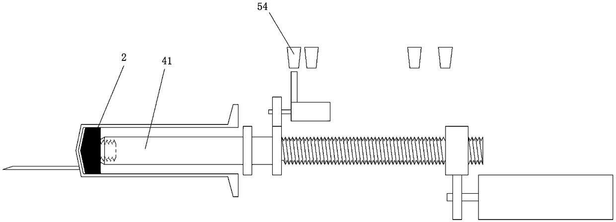
[0049] Different from the above-mentioned aseptic dispensing system, the difference of this embodiment is that the aseptic dispensing system is also provided with a plurality of photoelectric position sensors and a photoelectric shutter that can move with the joint 6. Through the cooperation of the photoelectric position sensor and the photoelectric shutter 6, the on-off of the circuit can be realized to control the rotation of the push rod motor 31 and the rod head rotation motor 44; figure 1 As shown, when the photoelectric barrier 6 senses the first photoelectric position sensor 51, the front push rod 41 is at the farthest position from the syringe barrel 1, and the front push rod 41 does not extend into Inside the syringe barrel 1, at this time, the rubber plug 2 is located at the front end of the syringe barrel 1; figure 2 As shown, the front push rod 41 gradually extends into the interior of the syringe barrel 1 under the drive of the actuating part. When the photoelect...

Embodiment 3

[0051] Different from the aseptic dispensing system described above, the difference in this embodiment is that the front push rod 41 is placed in an aseptic structure, and the syringe barrel 1 is in a sealed connection with the joint. Therefore, when the front push rod 41 is pushed into the syringe barrel 1, it is in a sterile environment.


PUM


Abstract

The invention discloses an aseptic dispensing system, which is used to realize automatic dispensing in a sterile state, comprising: a drug dissolving unit; a sterile unit, which is used to build a sterile environment, and the sterile unit includes a Dispensing push rod and a set of rods, the dispensing push rod is located in the sleeve rod; an actuating part, which is used to drive the dispensing push rod forward or backward; the dispensing push rod and the actuating part can be Detachable connection; the drug-dissolving unit is in a sealed connection with the sterile unit. Using the aseptic dispensing system for dispensing operations can free medical staff from the labor-intensive and time-consuming dispensing work, increase work efficiency, and reduce labor intensity; compared with traditional manual dispensing operations that are prone to errors, Using the aseptic dispensing system for automatic dispensing can greatly reduce erroneous operations due to manual operations, thereby avoiding the occurrence of medical accidents.

Description

technical field [0001] The invention relates to the field of dispensing devices, in particular to an aseptic dispensing system. Background technique [0002] At present, the most commonly used method of clinical infusion dispensing is manual dispensing. Nurses need to manually use syringes to mix the medicinal liquid, powder, etc. in the ampoule with other medicinal liquids, and then inject the mixed liquid into the infusion bottle or the patient. In this process, the nurse continuously operates the dispensing device to absorb and inject liquid, which is labor-intensive, low in efficiency, and prone to errors in manual operation. Moreover, the traditional dispensing device is exposed to the air for a long time, so that the dispensing push rod of the dispensing device is easily polluted during the dispensing operation. If bacteria are brought into the dispensing device, it is easy to cause contamination of the medicine; on the other hand , When dispensing medicine, nurses ar...

Claims


Application Information

Patent Timeline
Patent Type & Authority Patents(China)
IPC IPC(8): A61J1/20
CPCA61J1/2003A61J1/2048A61J1/2096
Inventor 张劲东张巍
Owner 哈尔滨碧研科技有限公司
Why Eureka
Try Eureka