Unmanned aerial vehicle charging base station

A technology for charging base stations and UAVs, applied in charging stations, electric vehicle charging technology, motor vehicles, etc., can solve the problems of UAV changing position, UAV charging port damage, UAV charging failure, etc., to achieve Ensure stability and safety, avoid charging failure, and ensure charging safety

Active Publication Date: 2020-03-24
陕西蓝天上航空俱乐部有限公司
View PDF5 Cites 3 Cited by
  • Summary
  • Abstract
  • Description
  • Claims
  • Application Information

AI Technical Summary

Problems solved by technology

[0003] The UAV needs to land on the tarmac of the base station when it is charging. In the windy area all year round, there are high requirements for the landing accuracy of the UAV, and it is difficult for the UAV to land on the designated position under the action of the wind, which affects The connection between the UAV and the base station will affect the charging efficiency of the UAV. At the same time, when the UAV is charging, the blowing of the wind will easily cause the UAV to change its position, which will cause the UAV to fail to charge, or even Cause damage to the charging port of the drone, accordingly, the present invention proposes a charging base station for the drone

Method used


Image

  • Unmanned aerial vehicle charging base station
  • Unmanned aerial vehicle charging base station
  • Unmanned aerial vehicle charging base station

Examples


Embodiment Construction

[0024] In order to make the technical means, creative features, goals and effects achieved by the present invention easy to understand, the present invention will be further described below in conjunction with specific embodiments.

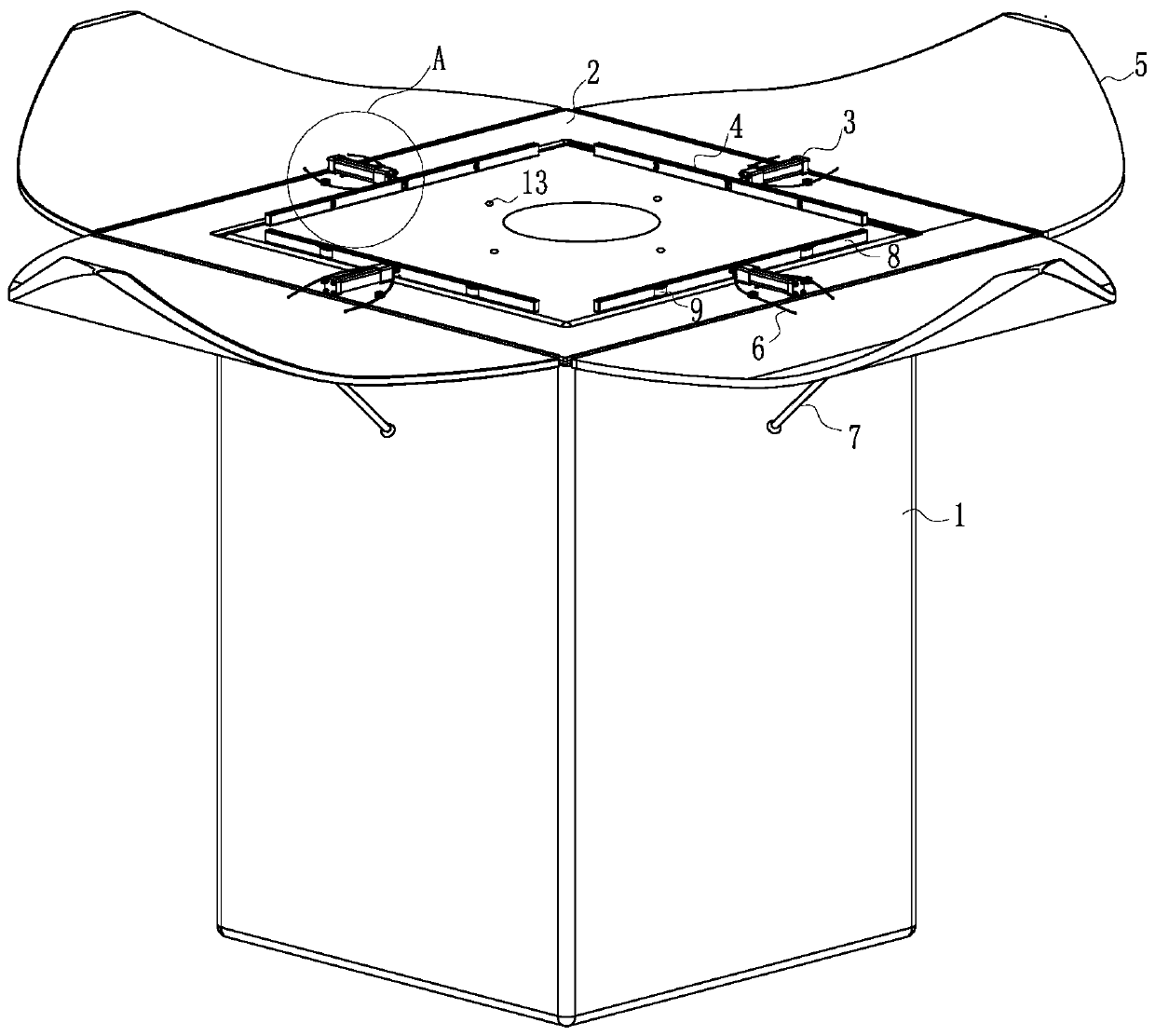
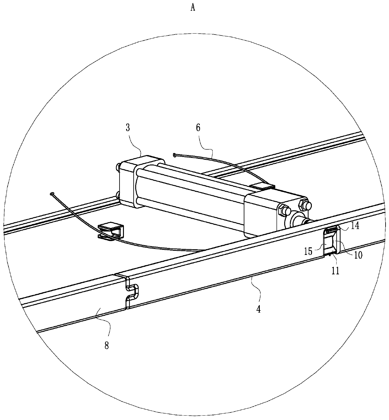
[0025] Such as Figure 1 to Figure 7As shown, a UAV charging base station according to the present invention includes a base station body 1, the base station body 1 is used for charging the UAV, and the top of the side wall of the base station body 1 is fixed with a mounting plate 2, so The mounting plate 2 is a square ring structure, and four push rod motors 3 are symmetrically fixed on the top of the mounting plate 2, and the output shaft ends of the four push rod motors 3 are fixed with push plates 4, and the push plates 4 When moving, it is used to adjust the position of the UAV. The side walls of the mounting plate 2 are hinged with windshields 5, and the windshields 5 are used for windshielding when the UAV is charged. The four windshields ...


PUM


Abstract

The invention belongs to the technical field of unmanned aerial vehicle charging. The unmanned aerial vehicle charging base station comprises a base station body, base station comprising a base station body, the base station body is used for charging an unmanned aerial vehicle. A installation plate is fixed to the top of the side wall of the base station body, the installation plate is of a squarering structure, four push rod motors are symmetrically fixed to the top end of the installation plate, push plates are fixed to the output shaft ends of the four push rod motors correspondingly, thepush plates are used for adjusting the position of the unmanned aerial vehicle when moving, and wind shields are hinged to the side walls of the installation plate correspondingly. Through the arrangement of the push plate and the rotating block, when the push rod moves, the position of the unmanned aerial vehicle is adjusted, so that the unmanned aerial vehicle is located at the charging part ofthe top end of the base station. Meanwhile, the rotating block is used for fixing the unmanned aerial vehicle, the unmanned aerial vehicle cannot shake during charging, charging failure is avoided, and the charging stability and safety of the unmanned aerial vehicle are guaranteed.

Description

technical field [0001] The invention belongs to the technical field of unmanned aerial vehicle charging, and specifically relates to an unmanned aerial vehicle charging base station. Background technique [0002] Unmanned aerial vehicle, also known as unmanned aircraft, is an unmanned aircraft controlled by radio remote control equipment and its own program control device. With the development of drone technology, drones have been widely used in people's production and life, such as surveying and mapping, cruise monitoring, etc. At present, most drones fly through batteries to provide energy, but the battery can provide The energy is limited. When the drone completes a flight and the battery is insufficient, it needs to enter the base station to charge or replace the battery in order to continue to perform tasks. The drone base station can automatically charge or charge the drone under human control. Replacement battery. [0003] The UAV needs to land on the tarmac of the ...

Claims


Application Information

Patent Timeline
Patent Type & Authority Applications(China)
IPC IPC(8): B64F1/00B64F1/12B60L53/30B60L53/36
CPCB60L2200/10B64F1/00B64F1/125B60L53/30B60L53/36Y02T10/70Y02T10/7072Y02T90/12
Inventor 占学宽陈岩闫羽
Owner 陕西蓝天上航空俱乐部有限公司
Why Eureka
Try Eureka