Device for transferring a fluid to a ship

Inactive Publication Date: 2015-08-25
TECH FRANCE SA
View PDF12 Cites 4 Cited by
  • Summary
  • Abstract
  • Description
  • Claims
  • Application Information

AI Technical Summary

Benefits of technology

[0013]The invention relates to providing a device for transferring a liquid between an installation for loading or unloading this

Problems solved by technology

A device of this type is not entirely satisfactory, since when seas are rough the relative movement of the ship in relation to the installation makes fixing a r

Method used


Image

  • Device for transferring a fluid to a ship
  • Device for transferring a fluid to a ship
  • Device for transferring a fluid to a ship

Examples


Embodiment Construction

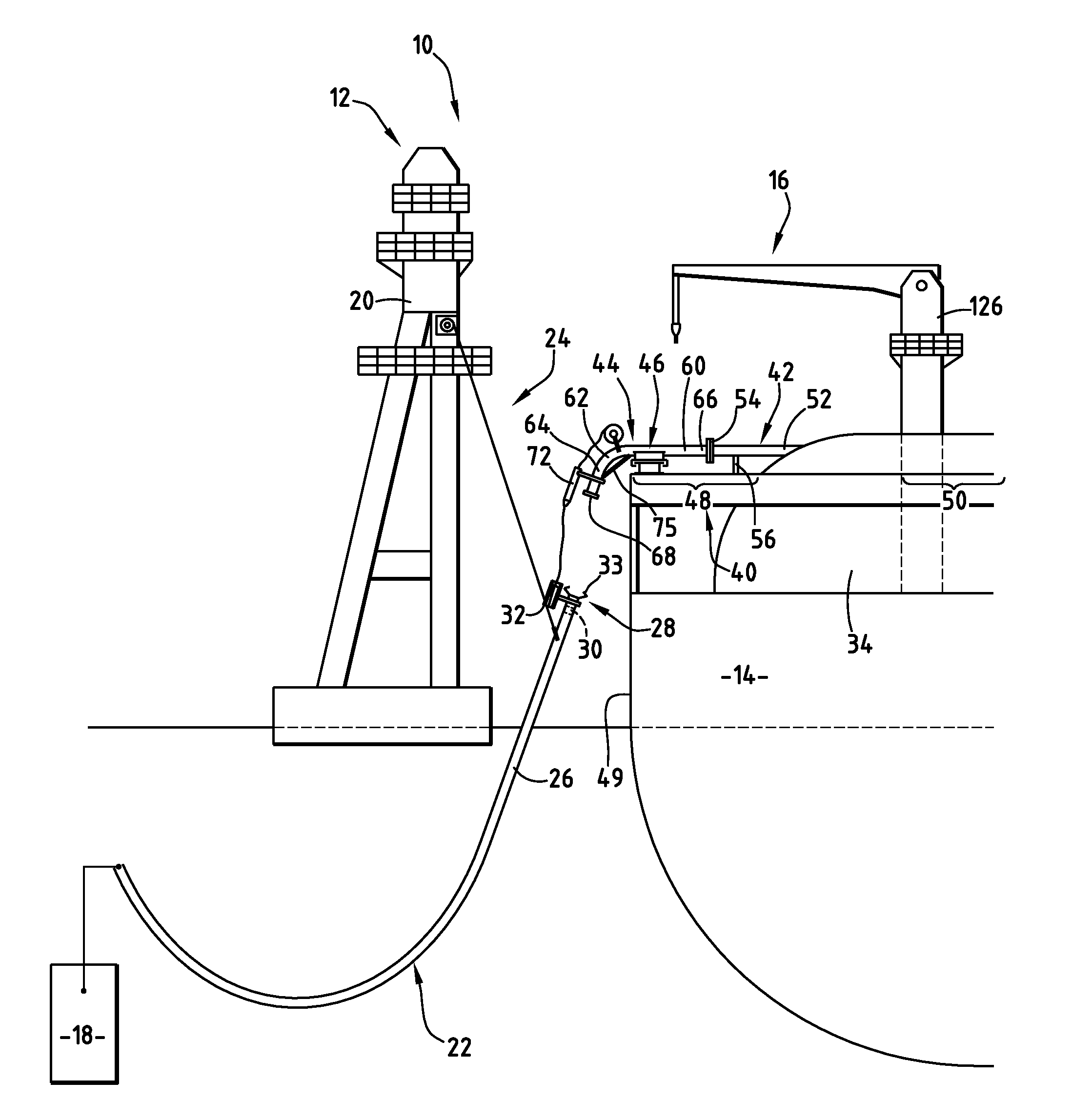
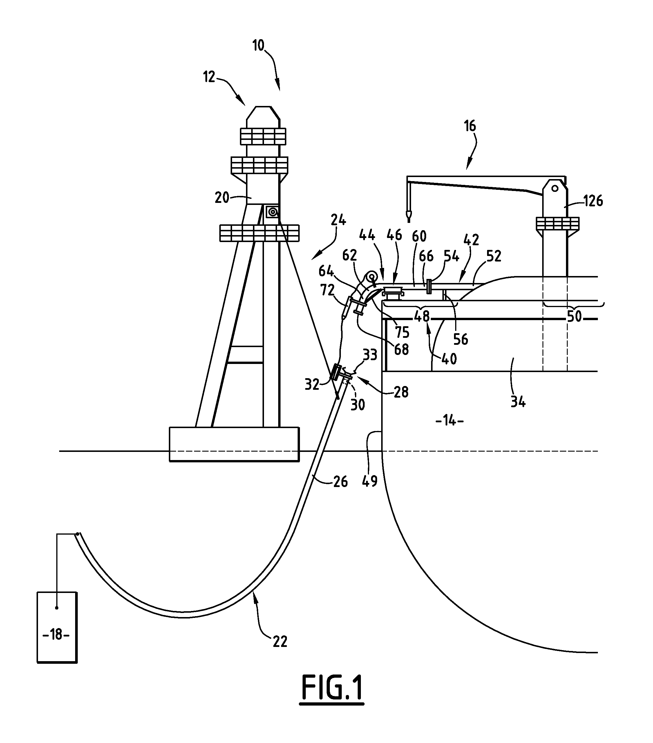
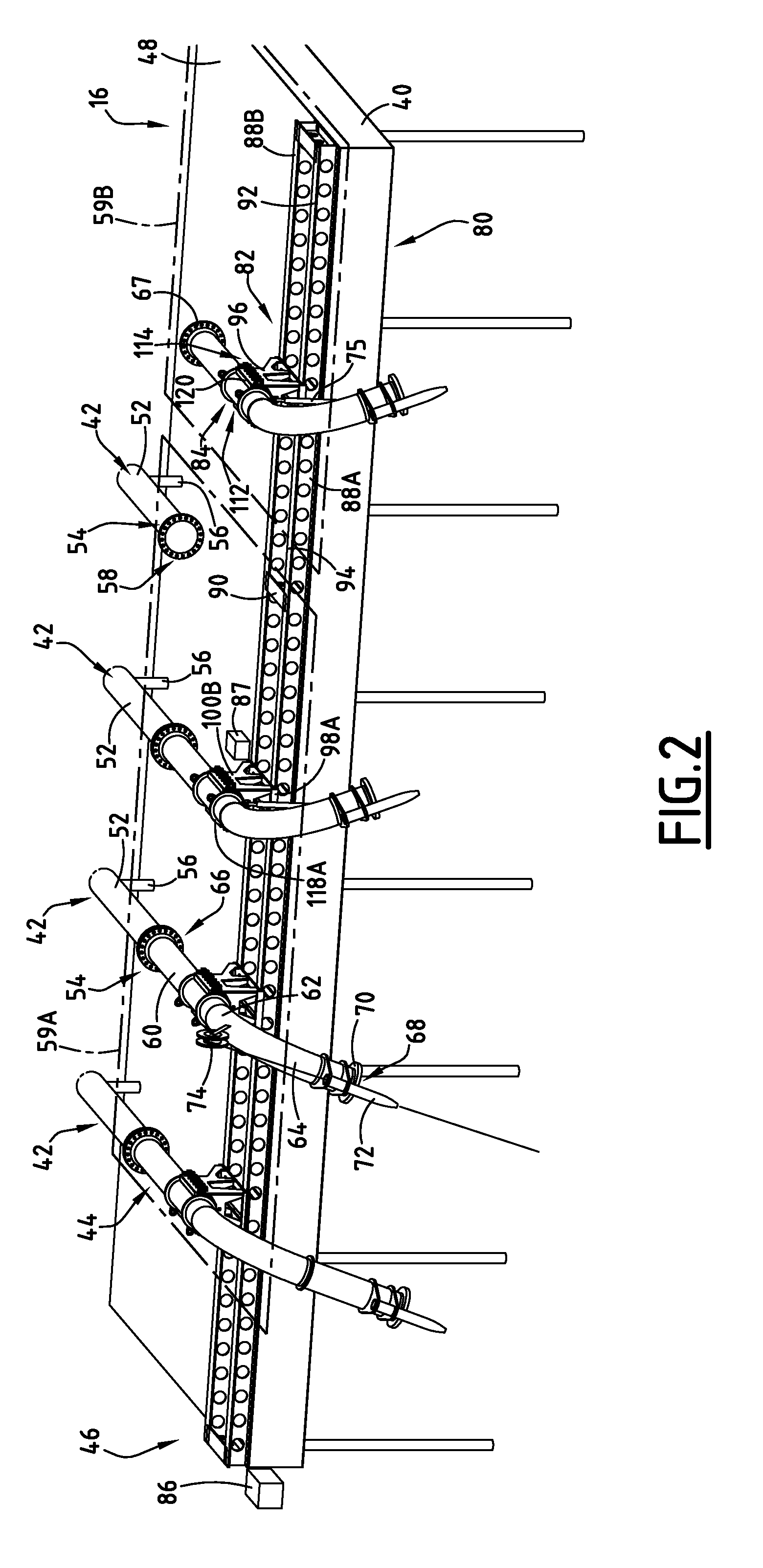
[0045]An assembly 10 for transferring a liquid, in particular a hydrocarbon composed of liquefied natural gas (LNG) for example, is shown in FIGS. 1 to 6.

[0046]The transfer assembly 10 comprises an offshore installation 12 for loading or / and unloading LNG, a ship 14 for storing and regasifying LNG, and a device 16, carried by the ship 14, for transferring LNG between the installation 12 and the ship 14.

[0047]The loading installation 12 comprises an LNG reservoir 18, a floating gantry crane 20 for unloading LNG, a flexible cryogenic hose 22 which connects the reservoir 18 to the gantry crane 20, and handling means 24 for manoeuvring the flexible hose 22.

[0048]The reservoir 18 is capable of collecting and storing LNG produced by LNG production installations. It is preferably located under the sea.

[0049]The floating gantry crane 20 carries the flexible hose 22 via the handling means 24.

[0050]The flexible hose 22 comprises a cryogenic hose 26 which is provided with a free end 28 to be c...


PUM

PropertyMeasurementUnit
Flexibilityaaaaaaaaaa
Heightaaaaaaaaaa
Distanceaaaaaaaaaa

Abstract

A filling platform connected to a ship, and at least one manifold which opens onto the platform. A detachable tubular connector connects the manifold to a fluid delivery hose carried by a delivery installation. At least one carriage conveys the connector over the platform. The carriage is moveable across the platform to convey the tubular connector over the platform between a storage position and an active position, in which latter position, the connector is fixed to the manifold. The system is applicable to the transfer of liquefied natural gas from offshore storage installations to tanker ships.

Description

CROSS REFERENCE TO RELATED APPLICATION[0001]The present application is a 35 U.S.C. §§371 national phase conversion of PCT / FR2007 / 001006, filed 18 Jun. 2007, which claims priority of French Application No. 06 05434, filed 19 Jun. 2006. The PCT International Application was published in the French language.BACKGROUND OF THE INVENTION[0002]The present invention relates to a device for transferring a liquid to a ship, of the type comprising:[0003]a loading platform intended to be integral with the ship;[0004]at least one manifold which opens out onto the platform;[0005]at least one displaceable tubular connection intended to connect the manifold to a flexible hose for distributing liquid, the flexible hose being supported by a liquid distribution installation.[0006]A device of this type is particularly suitable for transferring liquefied natural gas (LNG) between a transport ship and an offshore installation for storing the product and / or an installation for unloading this product, know...

Claims


Application Information

Patent Timeline
IPC IPC(8): B65B1/04B66B3/00B67D9/00B63B27/34B63B27/24B63B27/25B67C3/00B67D9/02
CPCB63B27/25B63B27/24B63B27/34B67D9/00Y10T137/8807
Inventor BIAGGI, JEAN PASCAL
Owner TECH FRANCE SA
Why Eureka
Try Eureka