Pulsation damper

a damper and pulsation technology, applied in the direction of shock absorbers, vibration dampers, pipe elements, etc., can solve the problems of pressure compensation in the flow channel, impair the damping, etc., and achieve the effect of reducing hydraulic energy, reducing pressure, and operating very reliably and cost-efficiently

Active Publication Date: 2015-08-25
MANN HUMMEL GMBH
View PDF10 Cites 0 Cited by
  • Summary
  • Abstract
  • Description
  • Claims
  • Application Information

AI Technical Summary

Benefits of technology

[0006]The objective is solved for a pulsation damper of the above-mentioned type by the fact that the housing has at least one hollow space communicating with the flow channel and in which at least one attenuator is disposed movably in axial direction. In this connection, the attenuator is movable in a purely mechanical way by the pressure pulsations. The supply of electrical energy is not required. Because of this, the pulsation damper operates very reliably and cost-efficiently. By moving the attenuator, mechanical work is performed and hydraulic energy is transformed into kinetic energy. As the volume flow is constant, the reduction of the hydraulic energy comes along with a reduction of the pressure. Thus, the pressure pulsations are dampened. Due to the movable attenuator, it could also be called a dynamic pulsation damper or a dynamic pressure peak damper.
[0007]The length of the attenuator in axial direction may be smaller than a length of the hollow space in such a way that a gap between the housing and the attenuator is generated in axial direction. When the attenuator is in a rest position, a first gap may be located upstream in axial direction and a second gap may be located downstream of the attenuator. The attenuator can have any shape, it has, however, always an end face directed upstream and downstream onto which the fluid pressure can act. If a pressure pulse occurs, the pressure differential between first gap and second gaps causes an axial displacement of the attenuator in flow direction. The first gap and the second gap preferably feature a width which exceeds a moving path of the attenuator at least two times, preferably five times. The gap width is in each case may preferably be at most a few millimeters, particularly preferred at most 1 mm. The gap widths can be chosen in such a way that the attenuator is not prevented from moving axially, i.e. the sum of the gap widths is bigger than the moving path of the attenuator. In this way, an optimal damping effect can be realized.
[0008]In an advantageous embodiment, an external diameter of the attenuator is at least sectionwise substantially equal to an internal diameter of the hollow space. Because of this, the formation of a bypass of the flow channel is prevented which would lead to a pressure compensation in the flow channel and impair a damping. The external diameter of the attenuator can only sectionwise, for example only at one place, substantially be equal to an internal diameter of the hollow space or over the whole length. A substantially equal diameter means in this case that, on the one hand, there is no form fit so that the attenuator is movable inside of the hollow space in axial direction and that, on the other hand, there is a smallest possible radial clearance so that the formation of a gap is prevented which would act as bypass for the fluid.
[0010]The attenuator can contribute to form the flow channel. The flow channel can feature a substantially constant cross-section. A constant cross-section offers the advantage that no pressure losses due to cross-sectional jumps occur.
[0014]The hollow space and the attenuator can feature a first section with a first external diameter and a second section with a second external diameter, wherein the second section is disposed downstream of the first section and wherein the second external diameter is smaller than the first external diameter. Because of this, two gaps, of which only one communicates with the flow channel, are formed downstream of the attenuator. The end face in relation to this gap can be called active surface, as the fluid pressure acts on it. The upstream directed end face of the attenuator and the downstream active surface feature different cross-sectional areas. Because of this, the damping effect can be increased. The width of the two gaps formed downstream can be equal. In the gap, which is not connected with the flow channel, the resilient element can be disposed advantageously.

Problems solved by technology

Because of this, the formation of a bypass of the flow channel is prevented which would lead to a pressure compensation in the flow channel and impair a damping.

Method used


Image

  • Pulsation damper
  • Pulsation damper
  • Pulsation damper

Examples


Embodiment Construction

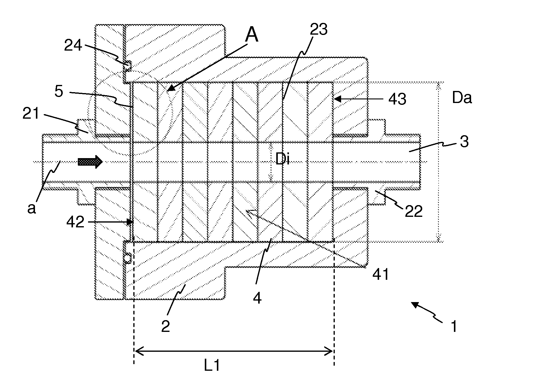
[0028]In the following, the invention will be explained by taking as an example an engine oil circuit in a motor vehicle. The pulsation damper 1 is insertable downstream of an oil pump into the engine oil line. In this connection, the pressure peaks caused by the oil pump for supplying the engine oil have to be damped. However, the pulsation damper 1 is also suitable for other fluids and applications in which pressure pulsations occur which have to be damped.

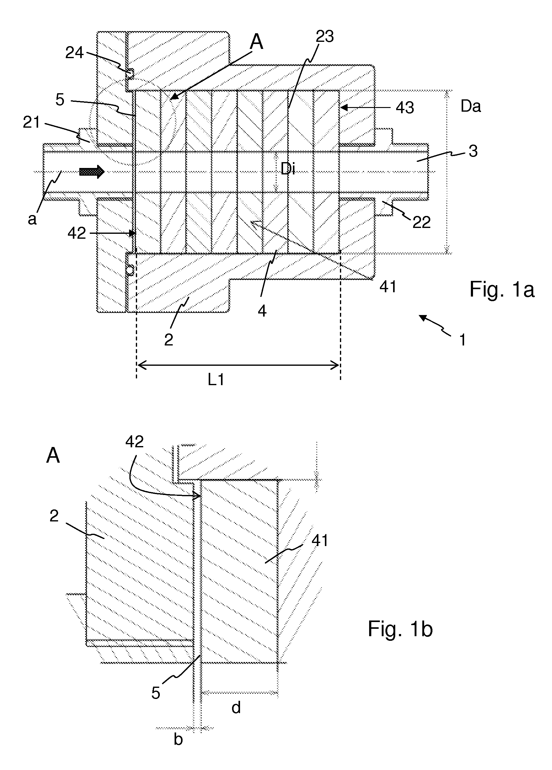
[0029]FIG. 1a shows a pulsation damper 1 according to a first embodiment in a sectional view. The pulsation damper 1 features a housing 2 rotationally symmetric around an axis “a” which is insertable as intermediate piece into a fluid-guiding line. In this connection, the connecting pieces 21, 22 of the fluid-guiding line feature the same internal diameter as the fluid-guiding line. The housing 2 is metallic, for example made of aluminum. In the housing 2 is formed a hollow space 23. The hollow space 23 is of cylindrical design....


PUM


Abstract

A pulsation damper (1) for damping pressure pulsations of a fluid is insertable into the fluid line as intermediate piece by forming an axial flow channel (3), and the pulsation damper (1) featuring a housing (2). The pulsation damper (1) is characterized by the fact that the housing (2) has at least one hollow space (23) communicating with the flow channel (3) and in which at least one attenuator (4) is disposed movably in axial direction.

Description

CROSS REFERENCE TO RELATED APPLICATIONS[0001]This application claims the benefit under 35 USC 119 of foreign application DE 10 2013 000 338.5 filed in Germany on Jan. 11, 2013, and which is hereby incorporated by reference in its entirety.TECHNICAL FIELD[0002]The invention relates to a pulsation damper for damping pressure pulsations of a fluid in a fluid line, wherein the pulsation damper is insertable into the fluid line as intermediate piece by forming an axial flow channel, and wherein the pulsation damper features a housing. The pulsation damper is especially suitable for being used in an engine oil circuit of an internal combustion engine, in particular of a motor vehicle.BACKGROUND OF THE INVENTION[0003]Pumps are often used to convey fluids. In this connection, many fluid pumps, for example vane pumps, generate in particular no constant volume flow at high speeds, but a time-varying volume flow with periodically occurring pressure pulsations. Such pressure peaks can damage co...

Claims


Application Information

Patent Timeline
Patent Type & Authority Patents(United States)
IPC IPC(8): F16F9/44F16L55/04
CPCF16F9/44F16L55/041
Inventor TESCHNER, MATTHIASGIAGOUNIDIS, PANAGIOTISKREMPELS, HELGEHERKOMMER, SIEGFRIED
Owner MANN HUMMEL GMBH
Why Eureka
Try Eureka