Dynamic characterisation of amplifier AM-PM distortion

a technology of am-pm distortion and dynamic characterisation, which is applied in the direction of electric devices, instruments, transportation and packaging, etc., can solve the problems of high heat dissipation, low dc to rf power conversion efficiency in this region, and only achieving the required linearity of traditional fixed bias amplifiers

Active Publication Date: 2015-08-25
SNAPTRACK
View PDF1 Cites 11 Cited by
  • Summary
  • Abstract
  • Description
  • Claims
  • Application Information

AI Technical Summary

Problems solved by technology

Traditional fixed bias amplifiers can only achieve the required linearity by ‘backing off’ the amplifier so that it normally operates at a power well below its peak power capability.
Unfortunately, the DC to RF power conversion efficiency in this region is very low.
As a consequence these designs dissipate considerable heat and reduce battery life when used in portable applications.
This results in the device getting hot, which can provide false characterisation data.
However with a pulse wave signal a problem may arise in measuring phase characteristics.
This may be at the expense of accepting a reduced system performance associated with another system characteristic.
In known characterisation methods, obtaining an accurate estimate of the AM-PM distortion of an envelope tracking amplifier is a known problem, as a result of phase wander in the test system itself.
Moreover this is a problem which is generally applicable to measuring test parameters for amplifiers in general, irrespective of whether they are part of an envelope tracking architecture.

Method used


Image

  • Dynamic characterisation of amplifier AM-PM distortion
  • Dynamic characterisation of amplifier AM-PM distortion
  • Dynamic characterisation of amplifier AM-PM distortion

Examples


Embodiment Construction

[0029]The invention is now described by way of example with reference to exemplary arrangements. The invention is not limited to the details of any described arrangement unless expressly stated. Aspects of the exemplary arrangements may be implemented in different combinations, and the invention is not limited to a specific combination of features by virtue of the presentation of an exemplary combination for the purposes of explaining the invention.

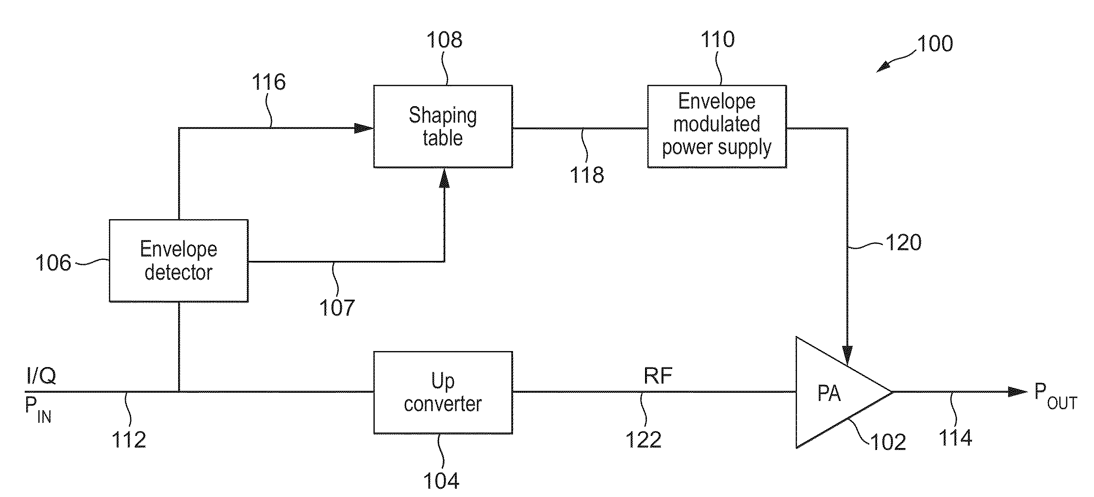
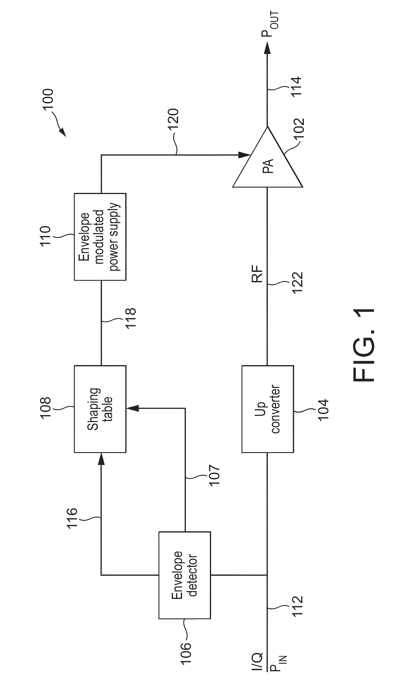
[0030]FIG. 1 illustrates an exemplary envelope tracking radio frequency (RF) power amplifier system 100 in which improvements in accordance with the present invention may be implemented. The envelope tracking power amplifier system 100 includes a power amplifier 102, an up-converter 104, an envelope detector 106, a shaping table 108, and an envelope modulated power supply 110.

[0031]A baseband input I / Q signal on line 112 forms an input to the up-converter 104, which generates an RF input signal for the RF power amplifier on line 122. The ...


PUM


Abstract

There is disclosed a method of determining an AM-PM distortion measurement for an amplifier, the method comprising: generating a test waveform to be provided to the input of the amplifier; periodically puncturing the test waveform with a fixed-level reference signal to generate a modified test waveform which alternates between test periods in which a portion of the test waveform is present and reference periods in which the fixed-level reference signal is present; measuring the amplifier AM-PM distortion in a test period; measuring the phase difference between the input and the output of the amplifier in reference periods either side of the test period; estimating a phase error in the test period in dependence on phase differences measured in the reference periods; and estimating the true amplifier AM-PM distortion by removing the estimated phase error from the measured amplifier AM-PM distortion.

Description

CROSS-REFERENCE TO RELATED APPLICATIONS[0001]British patent application GB 1205735.2, filed on Mar. 30, 2012, is incorporated herein by reference.FIELD OF THE INVENTION[0002]The invention relates to the determination of AM-PM distortion of an amplifier.[0003]The invention preferably but not exclusively relates to techniques for achieving efficient amplification of non-constant envelope signals. The invention particularly relates to the use of envelope tracking power supplies for amplification, incorporating shaping functions for shaping the envelope signal.[0004]The invention preferably, but not exclusively, relates to the amplification of radio frequency (RF) signals.DESCRIPTION OF THE RELATED ART[0005]Many modern communication systems typically use non-constant envelope modulation techniques to achieve high spectral efficiency. To avoid spectral spreading into adjacent communication channels, high linearity radio frequency (RF) amplification is required. Traditional fixed bias amp...

Claims


Application Information

Patent Timeline
Patent Type & Authority Patents(United States)
IPC IPC(8): H03F1/26H03F3/24H03F1/32G01R23/02H03F1/02G01R23/20
CPCG01R23/02H03F1/0222H03F1/3241H03F3/245G01R23/20H03F2200/102H03F2200/192H03F2200/195H03F2200/198H03F2200/201H03F2200/204H03F2200/207H03F2200/411G01R27/28H03F1/3288
Inventor CUMMINS, SHAUNWILLS, GARVINWIMPENNY, GERARD
Owner SNAPTRACK
Why Eureka
Try Eureka