
RF coil array having two or more switches built within each RF coil array element, compatible with both magnetic resonance and a temperature mapping

a technology of rf coil array and rf coil array element, which is applied in the direction of reradiation, measurement using nmr, instruments, etc., can solve the problems of low spatial sampling density of temperature, inability to accommodate hyperthermia systems, and pain in insertion of probes

Active Publication Date: 2015-08-25
GENERAL ELECTRIC CO
View PDF24 Cites 6 Cited by
  • Summary
  • Abstract
  • Description
  • Claims
  • Application Information

AI Technical Summary

Benefits of technology

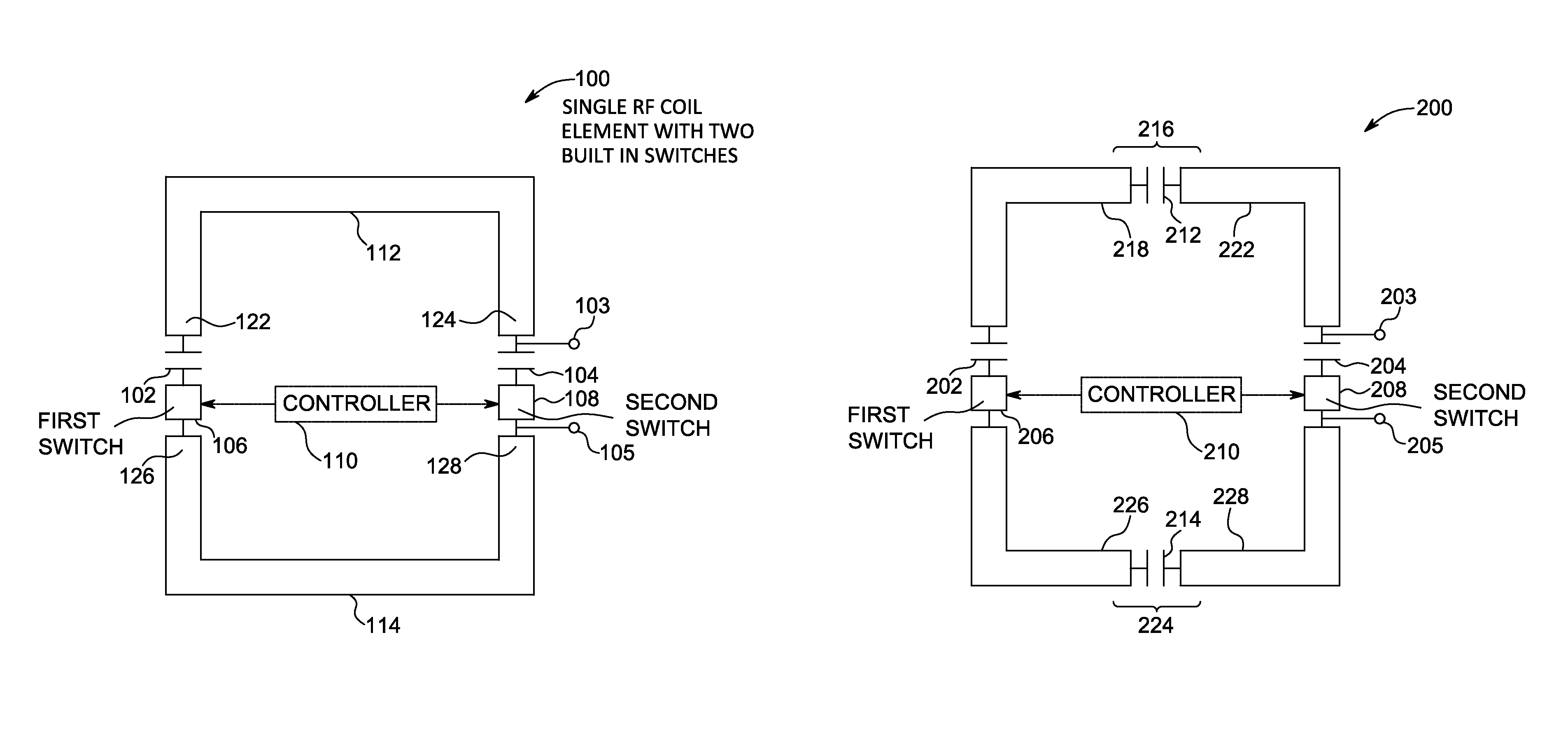
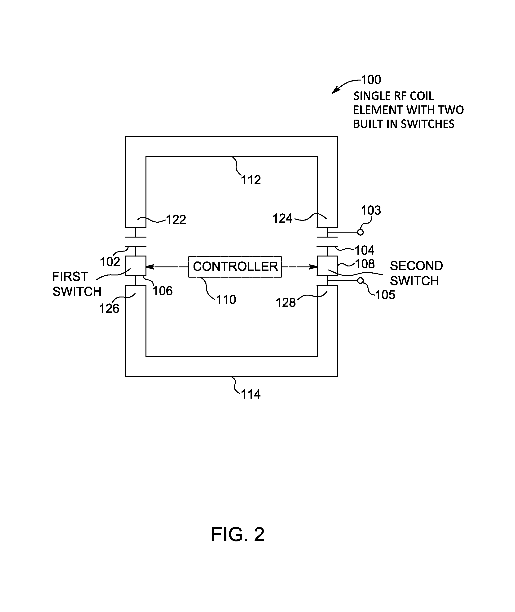
The patent text describes a system and method that allows for the simultaneous transmission or reception of multiple radio frequency signals through a plurality of coil elements. The coil elements are designed with first and second switches that can be turned on or off to change the mode of operation. In the first mode, the coil elements are split into upper and lower portions, and can only transmit or receive signals of a single frequency. In the second mode, the first and second switches are turned on, creating a loop coil that can simultaneously transmit or receive signals of multiple frequencies. The technical effect of this invention is the ability to transmit or receive multiple signals through a single system, enhancing the efficiency and reliability of wireless communication.

Problems solved by technology

However, only regions in close proximity to the probes can be monitored with these technologies, and thus, spatial sampling density of temperature is low.
Furthermore, probe insertion may be painful and hazardous.
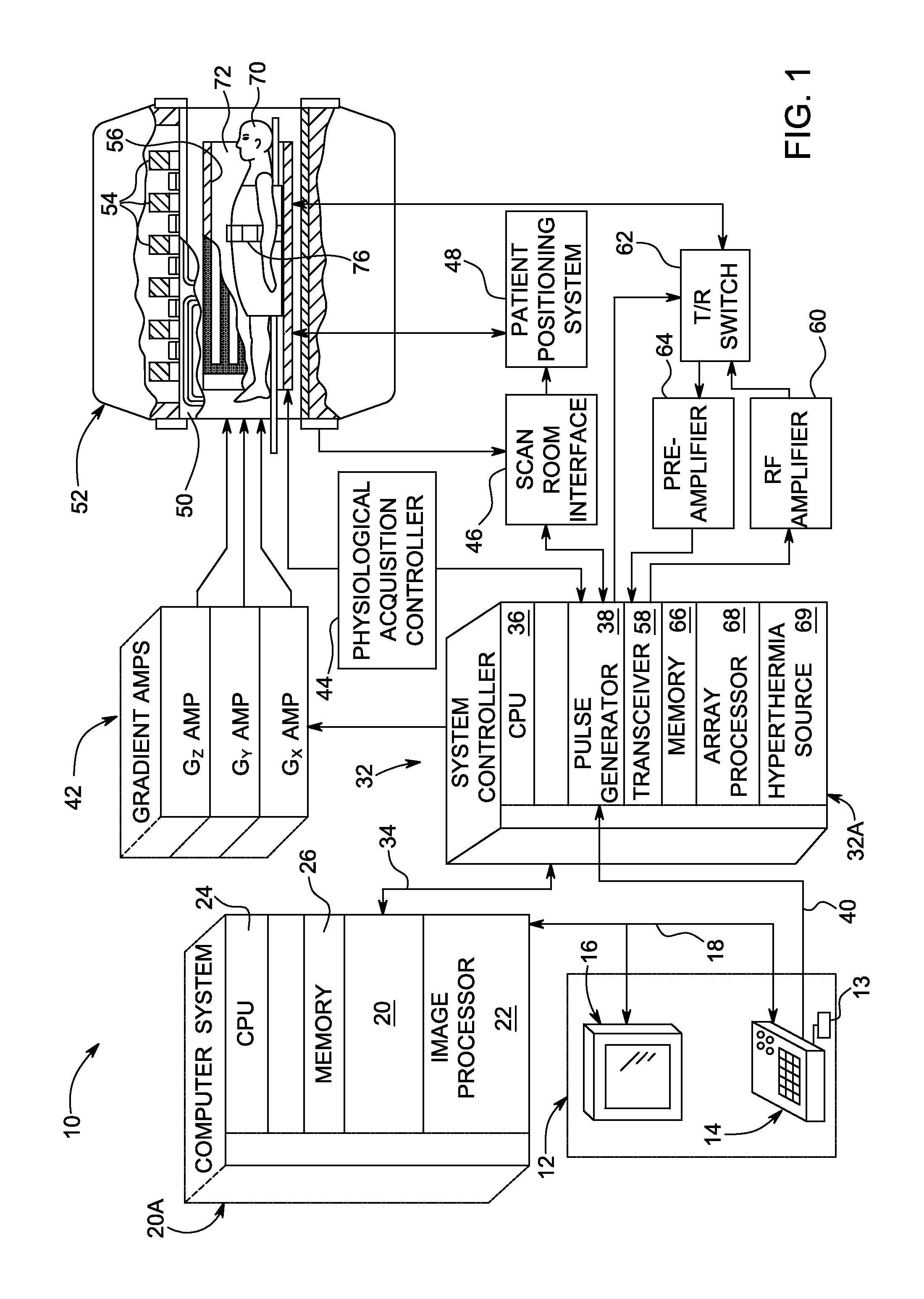
However, conventional MR systems are not designed to accommodate hyperthermia systems.
It is very challenging to combine hyperthermia and MR functions in a system by simply placing conventional RF hyperthermia apparatus inside a standard MR scanner.
Significant changes are typically required for both systems to avoid crosstalk and degraded MR thermometry data, which may significantly affect the ability to track the thermal dose delivered.

Method used


Image

  • RF coil array having two or more switches built within each RF coil array element, compatible with both magnetic resonance and a temperature mapping
  • RF coil array having two or more switches built within each RF coil array element, compatible with both magnetic resonance and a temperature mapping
  • RF coil array having two or more switches built within each RF coil array element, compatible with both magnetic resonance and a temperature mapping

Examples


Embodiment Construction

[0019]One or more specific embodiments of the present disclosure will be described below. In an effort to provide a concise description of these embodiments, not all features of an actual implementation are described in the specification. It should be appreciated that in the development of any such actual implementation, as in any engineering or design project, numerous implementation-specific decisions must be made to achieve the developers' specific goals, such as compliance with system-related and business-related constraints, which may vary from one implementation to another. Moreover, it should be appreciated that such a development effort might be complex and time consuming, but would nevertheless be a routine undertaking of design, fabrication, and manufacture for those of ordinary skill having the benefit of this disclosure.

[0020]Unless defined otherwise, technical and scientific terms used herein have the same meaning as is commonly understood by one of ordinary skill in th...


PUM


Abstract

A system including a plurality of coil elements is provided. Each coil element is arranged with a first switch and a second switch. In a first mode, the first switch and the second switch are turned off to split each coil element into a first upper coil portion and a second lower coil portion, to transmit first radio frequency signals. In a second mode, the first switch and second switch are turned on to transform each coil element into a loop coil to simultaneously transmit or receive multiple second radio frequency signals.

Description

BACKGROUND[0001]Many clinical studies have shown the effectiveness of adjuvant hyperthermia when it is used in conjunction with radiotherapy and chemotherapy for cancer treatment. Increased tumor cell kill-rate is attained when the temperature in a tumor remains within 41° C. to 43° C. for a predefined period of time, while safety considerations require that the temperature of normal healthy tissue remains below some predetermined limit. In hyperthermia treatment, it is therefore necessary to control the temperature throughout the heated volume. Temperatures can be measured by invasive means, such as thermocouples, thermistors, or fiber-optic probes. However, only regions in close proximity to the probes can be monitored with these technologies, and thus, spatial sampling density of temperature is low. Furthermore, probe insertion may be painful and hazardous.[0002]Magnetic resonance (MR) is a non-invasive and non-ionizing technique, which may produce anatomical images in any orient...

Claims


Application Information

Patent Timeline
Patent Type & Authority Patents(United States)
IPC IPC(8): G01R33/3415G01R33/36G01R33/48
CPCG01R33/3664G01R33/4808G01R33/3415G01R33/4804
Inventor YANG, XINGYEO, TECK BENG DESMONDCHU, XUFOO, THOMAS KWOK-FAHWU, JING
Owner GENERAL ELECTRIC CO
Learn More