Automobile shock absorber which uses permanent magnets and electromagnets

a technology of electromagnets and shock absorbers, which is applied in the field of shock absorbers, can solve the problems of limited buffering capacity of shock absorbing the limit of the shock absorbing capacity of the shock absorber foam and the bumper face, and the limitation of the shock absorber capacity of the magnet employing power, so as to reduce the damage of permanent magnets, prevent oxidation, and improve durability

Inactive Publication Date: 2015-09-01
DONGCHUN CO LTD
View PDF8 Cites 0 Cited by
  • Summary
  • Abstract
  • Description
  • Claims
  • Application Information

AI Technical Summary

Benefits of technology

[0011]Disclosed is a shock absorber provided in a bumper of a vehicle using permanent magnets and electromagnets in which the bumper has a structure to effectively absorb and buffer shock from a vehicle collision based on the standard vehicle operating speed of 60 m / h by means of an adaptive buffering capacity due to the repulsive force between the first permanent magnet and the second permanent magnet installed sequentially between the internal surface of a bumper face and the front surface of a vehicle along with the repulsive force of electromagnets, which are installed on the rear of the second permanent magnet and operated when the vehicle operating speed exceeds 60 km / h or when the distance between the object ahead and the driver's vehicle is in the range of about 6 to 8 m, wherein the durability of the permanent magnets being composed of a plurality of magnet blocks is extended by coating the magnet blocks with rubber or synthetic resin, and also the area of damage in the vehicle can be minimized at the time of collision.
[0012]The present invention provides a shock absorber of a vehicle employing permanent magnets and electromagnets, including: a first permanent magnet installed on the internal surface of the bumper face; a second permanent magnet installed on the front surface of a shock absorbing foam, which is installed on the front surface of the vehicle body, and has the same polarity as that of the first permanent magnet; and an electromagnet which is installed on the internal surface of the shock absorbing foam, and has the same polarity as that of the second permanent magnet when the vehicle operating speed exceeds the standard vehicle speed, wherein the first permanent magnet and the second permanent magnet are respectively composed of a plurality of partitioned magnet blocks with an appropriate size; and their external surfaces are coated with rubber or synthetic resin thereby reducing damage area at the time of vehicle collision, and maintaining the same level of magnetism permanently by preventing oxidation.
[0013]The present invention also provides permanent magnets and electromagnets with the same structure on the side doors of a vehicle thereby buffering and minimizing a collision impact due to the repulsive force at the time of vehicle collision on the sides of a vehicle.

Problems solved by technology

However, when the collision occurs while the vehicle is driven at a speed of over 30˜40 Km / h there is a limitation on the buffering capacity of the shock absorbing foam and the bumper face, and the shock absorbing foam are easily destroyed by the collision shock thus raising a problem.
However, the above vehicle bumper employing the magnetic power has also limitation in its shock absorbing capacity when the collision occurs while the vehicle is driven at a speed of over 60 km / h, when the vehicle body including both the bumper face and the shock absorbing foam will be seriously damaged and passenger in the vehicle cannot be protected from serious damage.
However, the above patent has problems that because the bumper face and the permanent magnet installed in a vehicle are formed as a single unit, respectively, they can be easily damaged in their entirety or malformed by the collision shock and because they are exposed to the outside of a vehicle they are vulnerable to oxidation process resulting in corrosion and their magnetic power also deteriorate according to time passage thus not functioning properly.

Method used


Image

  • Automobile shock absorber which uses permanent magnets and electromagnets
  • Automobile shock absorber which uses permanent magnets and electromagnets
  • Automobile shock absorber which uses permanent magnets and electromagnets

Examples


Embodiment Construction

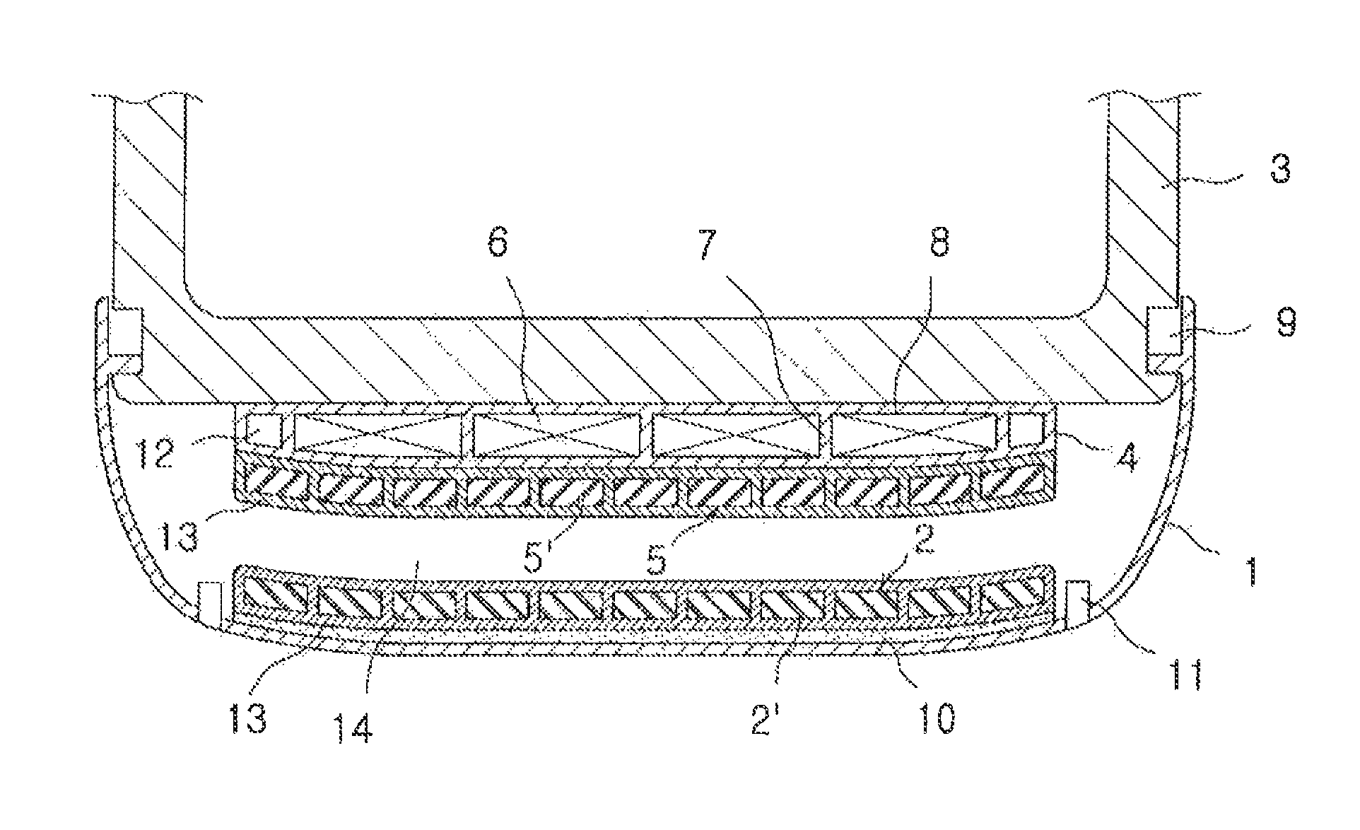
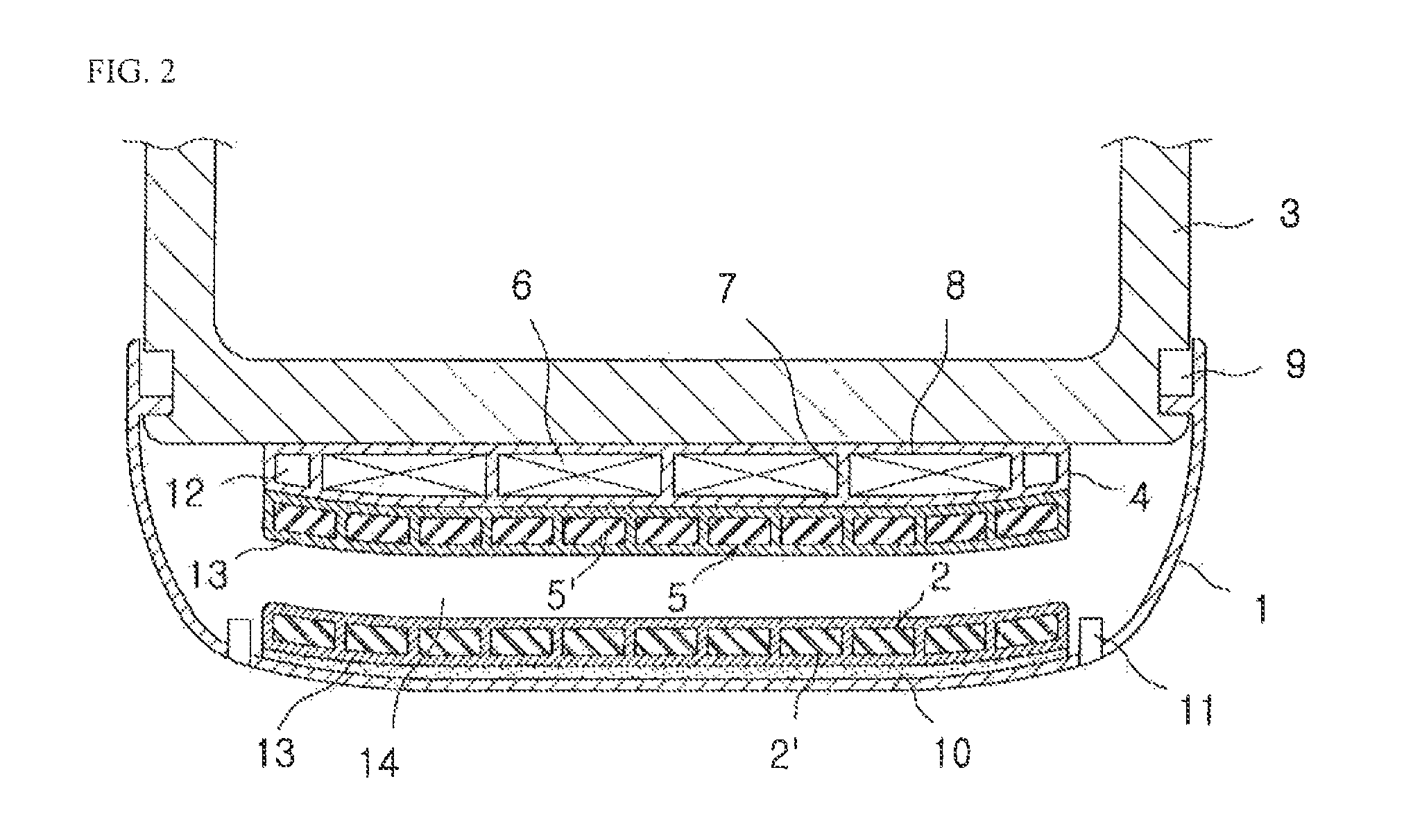
[0023]Hereinafter reference will now be made in detail to various embodiments of the present invention, examples of which are illustrated in the accompanying drawings and described below. While the invention will be described in conjunction with exemplary embodiments, it will be understood that present description is not intended to limit the invention to those exemplary embodiments. On the contrary, the invention is intended to cover not only the exemplary embodiments, but also various alternatives, modifications, equivalents and other embodiments, which may be included within the spirit and scope of the invention as defined by the appended claims.

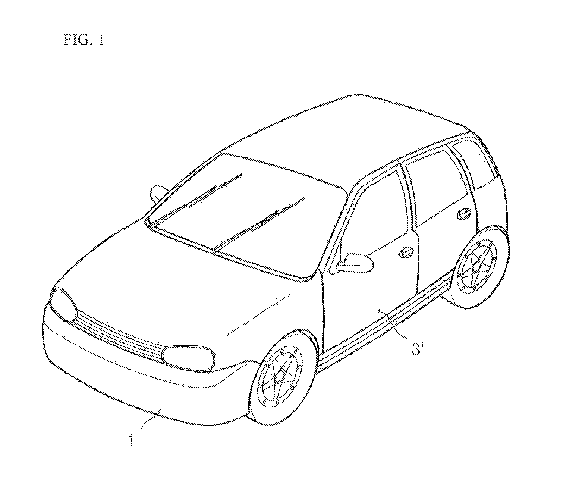
[0024]It is understood that the term “vehicle” or “vehicular” or other similar term as used herein is inclusive of motor vehicles in general such as passenger automobiles including sports utility vehicles (SUV), buses, trucks, various commercial vehicles, watercraft including a variety of boats and ships, aircraft, and the like, and inclu...


PUM

PropertyMeasurementUnit
speedaaaaaaaaaa
distance detecting sensoraaaaaaaaaa
polarityaaaaaaaaaa

Abstract

A shock absorber of a vehicle employing permanent magnets and electromagnets includes a first permanent magnet on an internal surface of a bumper face; a second permanent magnet on the front surface of a shock absorbing foam, which is installed on a front surface of the vehicle body and has the same polarity as the first permanent magnet; and an electromagnet on the internal surface of the shock absorbing foam, and has the same polarity as that of the second permanent magnet when the vehicle operating speed exceeds the standard vehicle speed, wherein the first permanent magnet and the second permanent magnet are respectively comprised of a plurality of partitioned magnet blocks; and their external surfaces are coated with rubber or synthetic resin thereby reducing damage.

Description

TECHNICAL FIELD[0001]The present invention relates to a shock absorber provided in a bumper of a vehicle using permanent magnets and electromagnets in which the bumper is configured to effectively absorb and buffer shock from a vehicle collision based on the standard vehicle operating speed of 60 km / h by means of an adaptive buffering capacity due to the repulsive force between the first permanent magnet and the second permanent magnet installed sequentially between the internal surface of a bumper face and the front surface of a vehicle, along with the repulsive force of electromagnets, which are installed on the rear side of the second permanent magnet and operated when the vehicle operating speed exceeds 60 km / h or when the distance between the object ahead and the driver's vehicle is in the range of about 6 to 8 m, wherein the durability of the permanent magnets being composed of a plurality of magnet blocks is extended by coating the magnet blocks with rubber or synthetic resin...

Claims


Application Information

Patent Timeline
Patent Type & Authority Patents(United States)
IPC IPC(8): B60R19/03B60R19/04B60R19/48H01F7/02
CPCB60R19/04B60R19/03B60R19/483H01F7/021B60R19/02B60R19/18
Inventor SON, SONG-NAM
Owner DONGCHUN CO LTD
Why Eureka
Try Eureka