Electromagnetic relay

a technology of electromagnetic relays and supporting springs, applied in the field of electromagnetic relays, can solve the problems of large height dimension of electromagnetic relays, adversely affecting the switching lifespan of contacts, and difficult to accurately process the supporting springs to the desired angle, etc., to suppress the generation of collision noise, simple structure, and easy adjustment

Active Publication Date: 2015-09-01
ORMON CORP
View PDF53 Cites 9 Cited by
  • Summary
  • Abstract
  • Description
  • Claims
  • Application Information

AI Technical Summary

Benefits of technology

[0006]Accordingly, it is an object of the present invention to provide an electromagnetic relay including a hinge spring that has a simple structure and in which adjustment can be easily carried out, and furthermore, that can suppress the generation of collision noise of when pivoting the moving iron without adversely affecting the pivoting operation of the moving iron.

Problems solved by technology

However, in the conventional electromagnetic relay, the supporting spring is arranged at the upper portion of the moving iron, which results into larger height dimension of the entire electromagnetic relay.
Furthermore, a bent structure of the supporting spring is complex, and it is difficult to accurately process the supporting spring to the desired angle.
Moreover, since the operation buffer spring acts to suppress the contact pressure, this adversely affects the switching lifespan of the contact.
Although the operation buffer spring needs to be formed into a substantially horseshoe shape, it is difficult to perform such processing at high accuracy.
Even when attempting to manually adjust the operation buffer spring and the return buffer spring, deformation tends to easily occur and the moving iron may not smoothly operate after the adjustment since the supporting portion of the moving iron is movably supported.
The work of assembling the moving iron is difficult in terms of the structure of the contact spring.Patent Document 1: Japanese Unexamined Patent Publication No. 2002-245917

Method used


Image

  • Electromagnetic relay
  • Electromagnetic relay
  • Electromagnetic relay

Examples


Embodiment Construction

[0026]An embodiment according to the present invention will be hereinafter described according to the accompanying drawings. In the following description, terms (e.g., terms including “up”, “down”, “side”, “end”) indicating a specific direction or position are used as necessary but the use of such terms are merely to facilitate the understanding of the invention that references the drawings, and it should be recognized that the technical scope of the invention is not to be limited by the meaning of such terms. Furthermore, the following description is merely illustrative in essence, and is not intended to limit the present invention, the applied articles and the applications thereof.

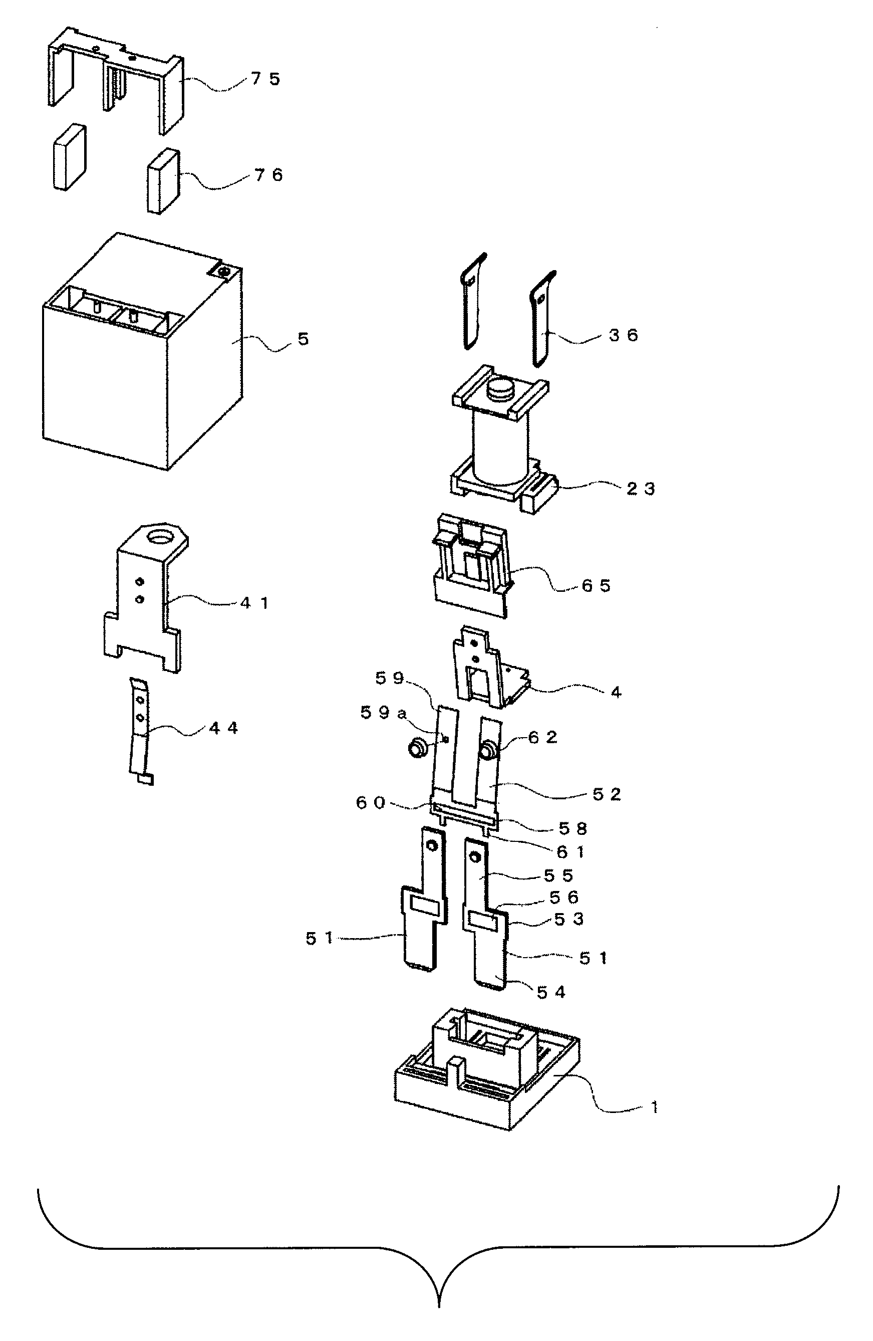
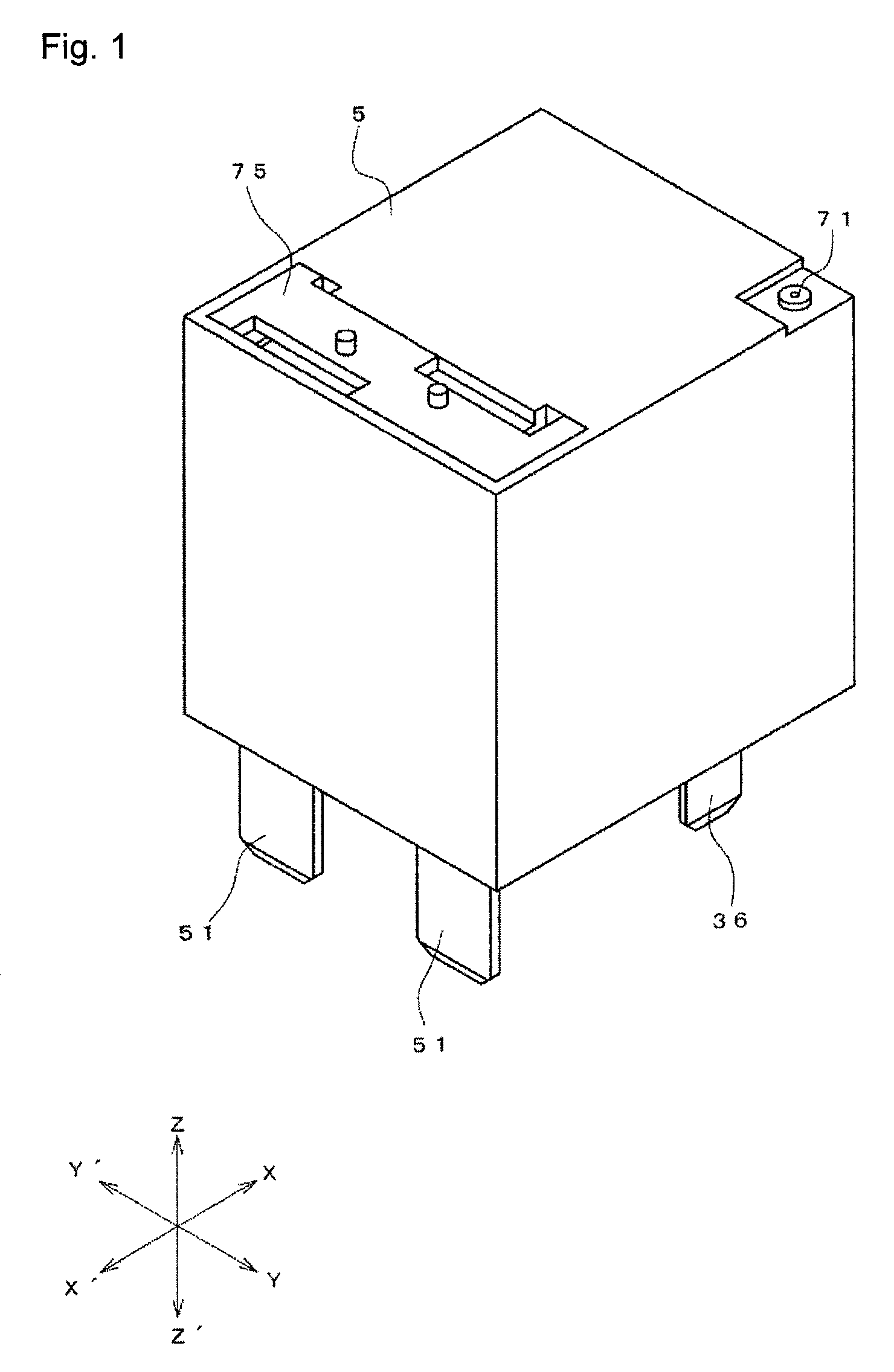
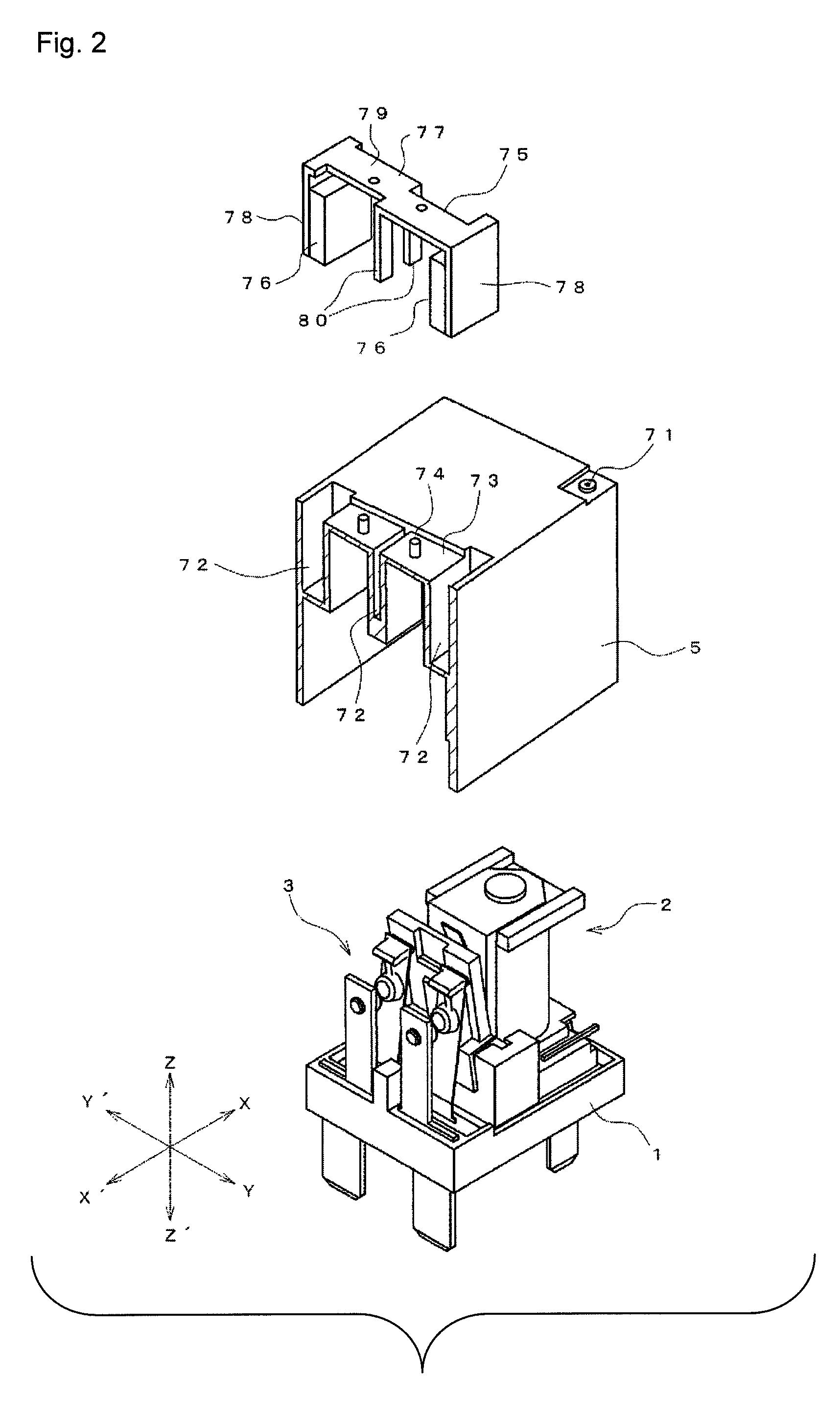
[0027]FIGS. 1 to 5 show an electromagnetic relay according to the one of the preferred embodiments of the present invention. The electromagnetic relay is obtained by arranging an electromagnet block 2, a contact switching unit 3, and a moving iron 4 on a base 1 and placing a case 5 thereon.

[0028]As shown...


PUM


Abstract

An electromagnetic relay including an electromagnet block having a rod-shaped iron core, a coil wound around the rod-shaped iron core, and a spool interposed between the coil and iron core. A yoke having one end section extends to a section at a side of a magnet pole section of the iron core. An end section of the yoke is arranged so that the magnet pole section has a gap on a base side. A moving iron is pivotably supported by an elastic support of a hinge spring. The electromagnet block is magnetized wherein a section drawn in the moving iron is drawn to the magnet pole section and pivoted to drive a contact switching unit. The hinge spring includes an elastic contacting portion extending toward an opposite side to the elastic support. The moving iron is integrated with a card member that comes in contact with the elastic contacting portion.

Description

CROSS REFERENCE TO RELATED APPLICATION[0001]This application is a U.S. National Phase application under 35 U.S.C. §371 of International Application No. PCT / JP2011 / 057133, filed on Mar. 24, 2011 and claims benefit of priority to Japanese Patent Application No. 2011-055721, filed on Mar. 14, 2011 of which full contents are added by herein.BACKGROUND OF THE INVENTION[0002]The present invention relates to an electromagnetic relay.[0003]Conventionally, an electromagnetic relay in which an electromagnet block formed by winding a coil around an iron core with a spool interposed therebetween is magnetized or demagnetized to pivot a moving iron, which is supported pivotably by a yoke swaged and anchored to the iron core, and to drive a movable touch piece so that a movable contact opens and closes with respect to a fixed contact of a fixed touch piece arranged facing the movable touch piece is known (see e.g., Patent Document 1). In such an electromagnetic relay, an operation buffer spring e...

Claims


Application Information

Patent Timeline
Patent Type & Authority Patents(United States)
IPC IPC(8): H01H51/22H01H50/26H01H51/06H01H50/30H01H9/40H01H9/44H01H50/02H01H50/28H01H50/54
CPCH01H51/06H01H50/26H01H50/305H01H9/40H01H9/443H01H50/02H01H50/28H01H50/54H01H50/24H01H50/30
Inventor SHINKAI, TETSUOMASUI, YASUYUKIYAMASHITA, TSUKASA
Owner ORMON CORP
Why Eureka
Try Eureka