Motor vehicle rear

a technology for motor vehicles and rear axles, applied in vehicle sub-unit features, understructures, transportation and packaging, etc., can solve the problems of affecting the performance of the vehicle, so as to achieve easy bendability, dissipate impact energy, and dissipate impact energy

Active Publication Date: 2015-09-08
DR ING H C F PORSCHE AG
View PDF6 Cites 19 Cited by
  • Summary
  • Abstract
  • Description
  • Claims
  • Application Information

AI Technical Summary

Benefits of technology

[0010]In the event of a rear crash, the impact energy loads the side wall substantially in the longitudinal direction. The side wall can act substantially as a compression bar, and therefore, in comparison to the back wall, correspondingly higher forces can be dissipated without component failure. In addition, in the event of component failure of the side wall, for example due to buckling, the side wall would tend to bend away from the traction battery or other object arranged or inserted with an interference fit into the receiving housing. Therefore, the risk of the side wall damaging the object arranged in the receiving housing is reduced. In addition, the side wall is generally part of a box-shaped structure, and therefore the side wall is clamped at a plurality of points along its longitudinal direction, including at least at an upper and / or lower edge. The side wall thus is correspondingly stiff and fails only in the event of a correspondingly increased buckling load. In the event of a particularly severe rear crash, impact energy that is not absorbed by the impact member can be conducted past the back wall via the reinforcing element to the side wall, from which the impact energy can be dissipated onto the supporting structure. Therefore, objects in the receiving housing will not be damaged by deformation of the receiving housing. Thus, a traction battery or other sensitive object can be protected from damage with little structural outlay.
[0020]A lock crossmember for forming a lock recess for a trunk lock may be connected to the left longitudinal member and to the right longitudinal member. The impact profile runs over its entire transverse extent with respect to the forward direction of travel below the lock recess in the direction of gravity. Thus, the impact profile can be below the lock recess in a vertical extension of the trunk lock, and the impact profile can be integrated into a back wall of the motor vehicle body in a manner that saves construction space. The lock crossmember can form a suitable cutout for the impact profile. The lock recess can define a vertical height level beyond which the impact profile does not project in the vertical direction. In particular, the impact profile does not, as a result, have any lugs protruding vertically laterally with respect to the lock recess. Thus, a high degree of stability and / or a high absorption capacity of impact energy for the impact profile can be achieved with little use of material.

Problems solved by technology

However, in the event of a particularly severe rear crash, it is possible that the impact profile is deformed sufficiently to strike against the receiving housing.
As a result, the impact energy is not introduced into the back wall of the receiving housing, or at least is reduced to such an extent that, in the event of a rear crash, for example with a speed difference of 50 km / h, the back wall of the receiving housing is not pressed into the interior of the receiving housing to such an extent that a traction battery in the receiving housing and / or a battery cell can be damaged by the back wall.
In addition, in the event of component failure of the side wall, for example due to buckling, the side wall would tend to bend away from the traction battery or other object arranged or inserted with an interference fit into the receiving housing.
The side wall thus is correspondingly stiff and fails only in the event of a correspondingly increased buckling load.
In particular, the reinforcing element protrudes from the impact profile in the forward direction of travel, and therefore, even when plastic deformation of the impact profile has occurred, the impact profile will not strike an easily deformable region of the back wall.

Method used


Image

  • Motor vehicle rear
  • Motor vehicle rear
  • Motor vehicle rear

Examples


Embodiment Construction

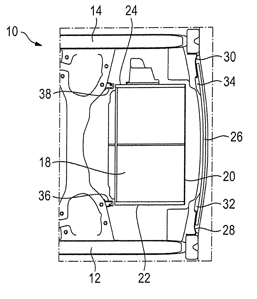
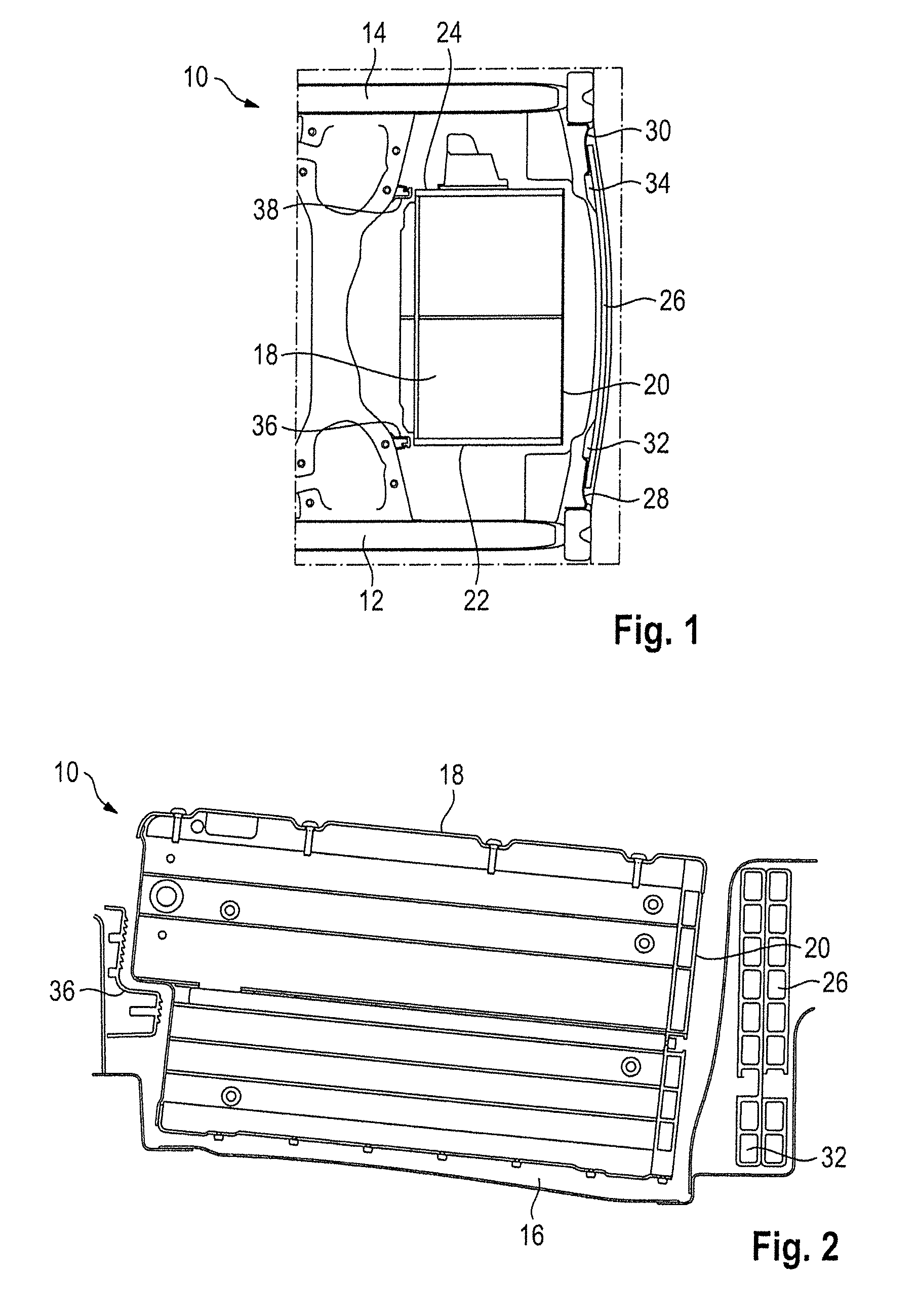
[0027]The vehicle rear 10 illustrated in FIGS. 1 and 2 has left and right longitudinal members 12 of a supporting structure of a motor vehicle. A receiving recess 16 is between the left and right longitudinal members 12 and 14 and receives a receiving housing 18 for a traction battery. The receiving housing 18 is configured as a box or a cube and has a back wall 20 connected to left and right side walls 22 and 24.

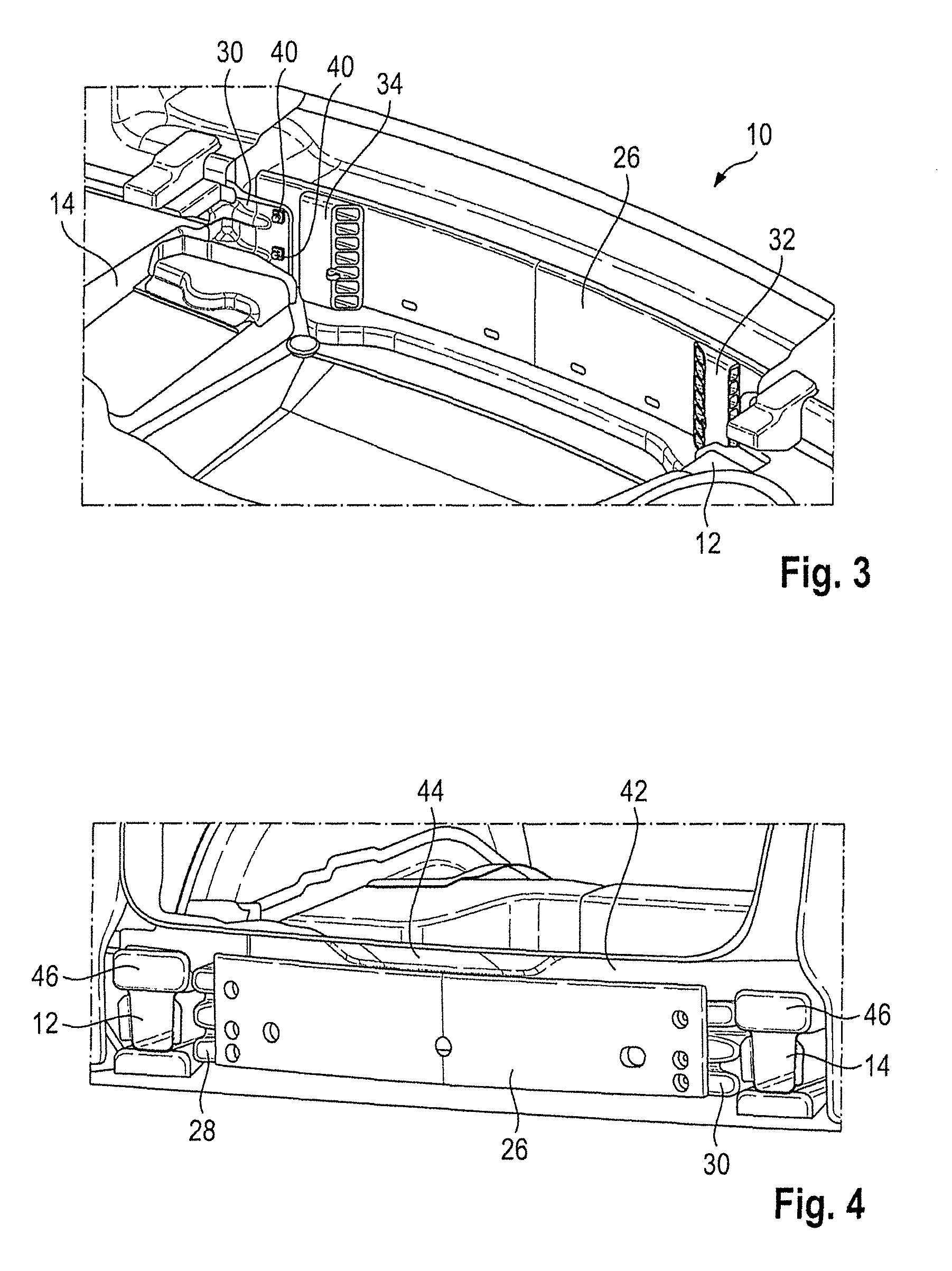
[0028]A rearwardly convex impact profile 26 is provided to protect the traction battery in the receiving housing 18 in the event of a rear crash. The impact profile 26 is connected on an inner side of the left longitudinal member 12 via an angular left bracket 28 and on an inner side of the right longitudinal member 14 via an angular right bracket 30. A left reinforcing element 32 is connected to the impact profile 26 in the longitudinal direction behind the left side wall 22, while a right reinforcing element 34 is connected to the impact profile 26 in the longitudinal dir...


PUM


Abstract

A motor vehicle rear (10) has left and right longitudinal members (12) forming a supporting structure of the motor vehicle. A receiving housing (18) is arranged between the longitudinal members (12) for receiving a traction battery. The receiving housing (18) has a left and right side walls (22, 24) running in the forward direction of travel. A back wall (20) is connected to the left and right side walls (22) and running transverse to the forward direction of travel. An impact profile (26) is connected to the left and right longitudinal members (12, 14) and absorbs impact energy in the event of a rear crash. Left and right reinforcing elements (32 34) connect the impact profile (26) to the respective left and right side walls (22, 24) for reinforcing the impact profile (26) and conducting away some of the impact energy into the left and right side walls (22, 24).

Description

CROSS REFERENCE TO RELATED APPLICATION[0001]This application claims priority under 35 USC 119 to German Patent Appl. No. 10 2013 114 311.3 filed on Dec. 18, 2013, the entire disclosure of which is incorporated herein by reference.BACKGROUND[0002]1. Field of the Invention[0003]The invention relates to a motor vehicle rear that is configured to receive an object, such as a traction battery for purely electrical drive of the motor vehicle.[0004]2. Description of the Related Art[0005]U.S. Pat. No. 8,708,401 discloses a motor vehicle rear with a motor vehicle battery arranged in the rear region of the motor vehicle. An impact frame for absorbing impact energy is provided between a bumper and the motor vehicle battery to protect the motor vehicle battery in the event of a rear crash. The impact frame has a rear bow connected to a trapezoidal front bow via deformable structures running in the longitudinal direction. The front bow has a subsection that runs in the transverse direction paral...

Claims


Application Information

Patent Timeline
Patent Type & Authority Patents(United States)
IPC IPC(8): B60K1/04B62D21/15B60R19/18
CPCB62D21/152B60K1/04B60R19/18B60K2001/0416B60R2019/247B60R2019/1806B60Y2306/01
Inventor EBERLE, WILFRIEDKLAMSER, HERBERTWIERSCHEM, FRANZ-RUDOLFHEKMANN, GERALDHAAG, DANIEL
Owner DR ING H C F PORSCHE AG
Why Eureka
Try Eureka