
Apparatus systems and methods of sensing chemical bio-chemical and radiological agents using electrophoretic displays

a technology of electrophoretic display and chemical biochemical, applied in the direction of instruments, beam/ray focussing/reflecting arrangements, dosimeters, etc., can solve the problem of non-optimized electronic paper being sensitive to high-energy radiation

Active Publication Date: 2015-09-08
US GOVT REPRESENTED BY SEC OF THE NAVY CHIEF OF NAVAL RES ONR NRL
View PDF10 Cites 4 Cited by
  • Summary
  • Abstract
  • Description
  • Claims
  • Application Information

AI Technical Summary

Benefits of technology

The patent describes how to use electrophoretic displays to detect chemicals, biological agents, and radioactivity using a radioactive isotope called Caesium-137 (Cs-137). The electronic paper used in the display is irradiated with the Cs-137 source, and the particles within the paper change charge when exposed to the radiation. The change in charge results in a movement of the particles, which causes a visible difference in the gray-scale of the display. The patent also discusses how the sensitivity of the display depends on the energy and dose of the radiation, the type of particles, and other factors such as the zeta potential and solution viscosity. The patent provides a rough estimate of the number of particles that will move based on the dose and energy of the radiation. Overall, the patent provides a technical solution for detecting radiation using electrophoretic displays.

Problems solved by technology

Thus, non-optimized electronic paper is sensitive to high energy radiation.

Method used


Image

  • Apparatus systems and methods of sensing chemical bio-chemical and radiological agents using electrophoretic displays
  • Apparatus systems and methods of sensing chemical bio-chemical and radiological agents using electrophoretic displays
  • Apparatus systems and methods of sensing chemical bio-chemical and radiological agents using electrophoretic displays

Examples


third embodiment

[0055] the general sensing schema, moving particles within the micro-container (such as the PDMS micro container 602), are applied to sensing biological and / or chemical agents. In order for the biological and / or chemical agents to react with the particles, a semipermeable membrane or container enclosure is needed. The semipermeable membrane also adds additional selectivity.

[0056]Furthermore, the mobility of the particles within the micro-container is a function of the zeta potential. Sensing can also be accomplished by modifying the zeta potential, e.g. change in pH value, ion concentration change.

[0057]Additionally, the detection sensitivity can be estimated for chemical agents, as follows: Organophosphate (OP) compounds are significant environmental and food chain pollutants because they are used intensively as pesticides, insecticides, and chemical-warfare agents. OP can react with functionalized carbon particles in a two electron reaction, according to G. Liu, Y. Lin “Electroche...

first embodiment

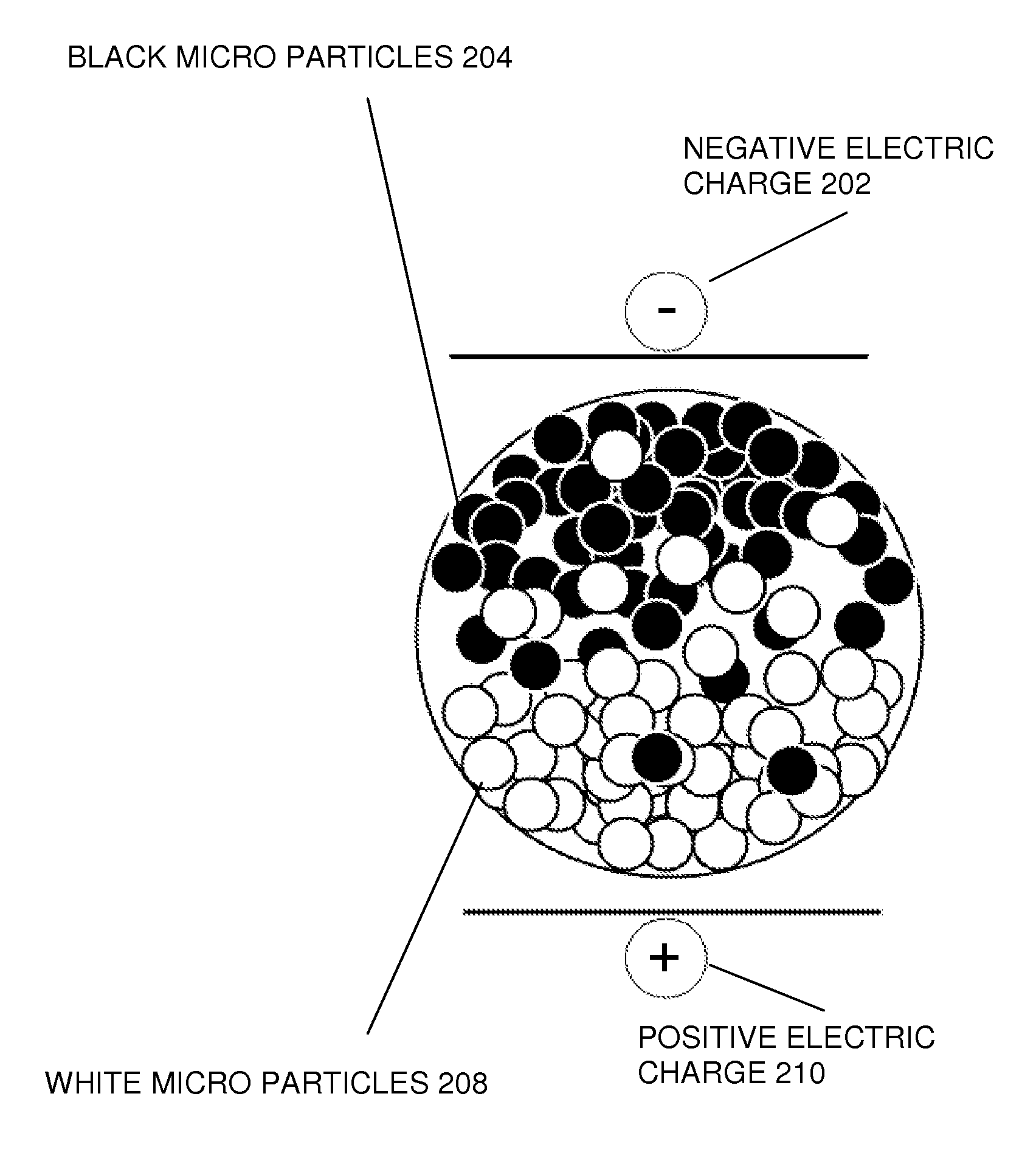
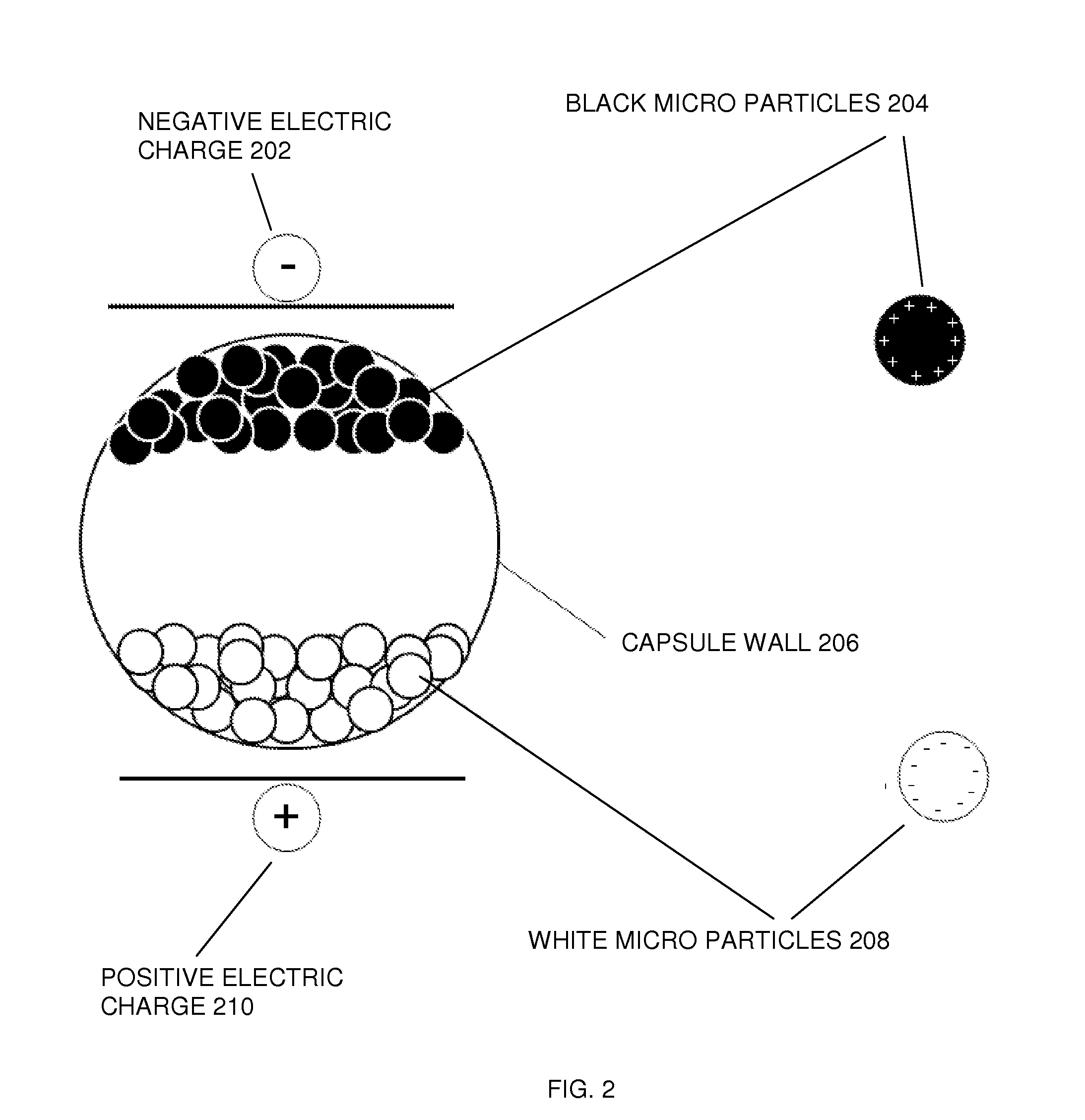
[0058] a method 800 of detecting, sensing and indicating exposure to a high energy ionizing radiation, (on and / or using) an electrophoretic display 302 having an electronic paper 102 is disclosed herein. The electronic paper 102 contains a plurality of transparent micro-containers, and residing in the plurality of transparent micro-containers are a plurality of positively charged black particles, such as black micro particles 204 and a plurality of negatively charged white particles, such as white micro particles 208. The visual appearance of the electronic paper 102 depends on a position of the plurality of charged particles, where the different charged particles are made of at least two different types of semiconducting materials having oppositely charged states. The size of the charged particles ranges from about 200 nm up to about 5 micrometers.

[0059]Referring to FIG. 8 and FIG. 3, and according to the first exemplary embodiment, at an operation “start”802 (hereafter “the operat...

second embodiment

[0067]Referring to FIG. 1, FIG. 6A, FIG. 6B, and FIG. 9, a method 900 of detecting, sensing and indicating an exposure to a plurality of bio-chemical agents involving charge transfer, (on and / or using) an electrophoretic display having electronic paper, is disclosed herein. The electronic paper 102 contains a plurality of microcontainers such as the PDMS micro container 602, and the plurality of microcontainers have and / or can be a plurality of transparent semipermeable membrane micro-sphere enclosures. Residing in the plurality of transparent semipermeable membrane micro-sphere enclosures are a plurality of positively charged functionalized black carbon particles and a dielectric colloidal fluid. This fluid can be a solution formed by the plurality of charged particles. Furthermore, a visual appearance of the electronic paper depends on a position of the plurality of charged particles, the method of detecting, sensing and indicating the exposure to the plurality of bio-chemical ag...


PUM

PropertyMeasurementUnit
diametersaaaaaaaaaa
diametersaaaaaaaaaa
diametersaaaaaaaaaa

Abstract

Caesium-137 irradiates electronic paper. An incoming gamma-ray from the Cs-137 interacts with a particle inside a micro-container by generating a recoil electron and / or a hole. Because the recoil electron physically leaves the particle, the particle is charged depending on the dose from the radiation source. And, the charge of the particles change, which results in a movement of the particles within the micro-container. After refreshing the electronic paper, a visible difference in the gray-scale can be seen. Thus, the visible difference in the gray-scale is an effect caused by the irradiation of the electronic paper, showing sensitivity to high energy radiation—thus, non-optimized electronic paper is sensitive to high energy radiation and can be used as a radiation dosimeter. In addition, electronic paper can be used for sensing chemical and bio-chemical agents, as well as detecting high energy radiation.

Description

FIELD OF THE INVENTION[0001]The present invention relates to applications involving public, civilian and / or military first responders to high energy radiation, chemical or bio-chemical agents. In particular, the present invention presents a method, apparatus and system using a display device for reliable, combined detecting / sensing and displaying and / or indicating exposure to high energy radiation chemical and / or bio-chemical agents.BACKGROUND OF THE INVENTION[0002]Electronic paper was developed in 1992 at Xerox Palo Alto Research Center (PARC) by N. Sheridan as a new type of display technology. According to M. E. Howard, E. A. Richley, R. Sprague, and N. K. Sheridon, “GYRICON electronic paper”, J. Soc. for Information Display, Vol. 4, pp. 215, 1998, this news type of display technology was called “GYRICON” and combined advantages of regular paper and electronic displays. Sheridan fabricated a rubber like sheet containing thousands of tiny balls. Half of the balls where white colore...

Claims


Application Information

Patent Timeline
Patent Type & Authority Patents(United States)
IPC IPC(8): G01T1/02G02F1/167H01J3/14
CPCG01T1/02G02F1/167H01J3/14
Inventor CHRISTOPHERSEN, MARCPHLIPS, BERNARD F.
Owner US GOVT REPRESENTED BY SEC OF THE NAVY CHIEF OF NAVAL RES ONR NRL
Learn More