
Rotation anode X-ray tube

a technology of rotation anode and x-ray tube, which is applied in the cooling of x-ray tubes, x-ray tubes, x-ray tube vessels, etc., can solve the problems of increasing the temperature of the anode target, requiring intensive cooling, and requiring enormous heat generation of the recoil electron capture structure. achieve the effect of high reliability and long life span

Active Publication Date: 2007-06-21
CANON ELECTRON TUBES & DEVICES CO LTD
View PDF5 Cites 0 Cited by
  • Summary
  • Abstract
  • Description
  • Claims
  • Application Information

AI Technical Summary

Benefits of technology

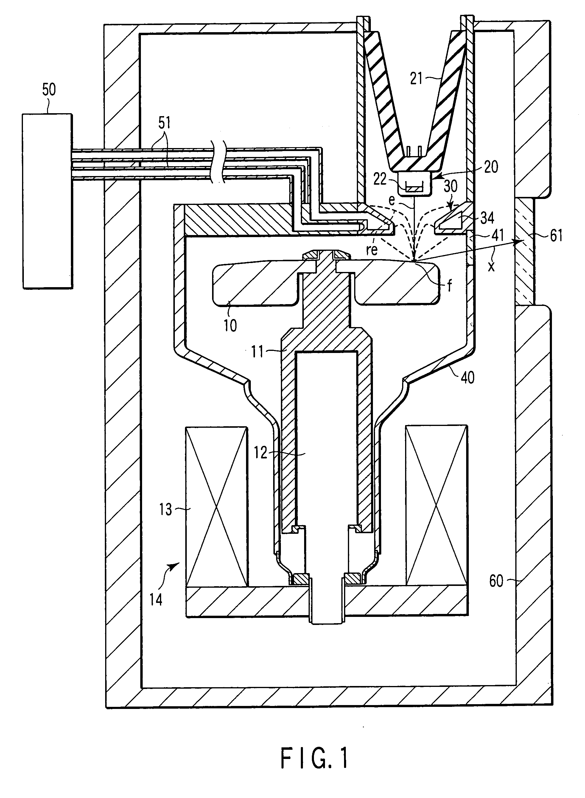
The present invention aims to provide a highly reliable rotation anode X-ray tube with a long life span. To achieve this, the invention includes a recoil electron capturing structure that surrounds the electron emitting source and the anode target, and a vacuum envelop that keeps the tube at a predetermined degree of vacuum. The invention also includes a specific crystal orientation for the recoil electron capturing structure. The use of these features results in a longer life span for the rotation anode X-ray tube and improved reliability.

Problems solved by technology

Further, heat generated by recoil electrons causes a rise in temperature of the anode target or the like.
Therefore, heat generation of the recoil electron capturing structure is made enormous, which requires intensive cooling.
When secondary recrystallization proceeds, generation of gas from crystalline boundaries, reduction in surface roughness, and the like are brought about by boundary sliding or the like, which results in deterioration in withstand voltage.
Namely, there is a defect that the life span is short in a recoil electron capturing structure formed from pure copper as a material.
However, because oxide-dispersion-strengthened copper and strengthened copper alloy have ductility lower than that of pure copper, when crystal breaking is once brought about, the breaking becomes cracks, which rapidly proceed and finally lead to atmospheric penetration in some cases.
Namely, there is a defect that it is impossible to keep vacuum tight at the inside of the vacuum envelop in a recoil electron capturing structure formed from oxide-dispersion-strengthened copper or strengthened copper alloy as a material.
Therefore, in some cases, the rotation anode X-ray tube is made unusable at a point in time when atmospheric penetration is brought about finally due to cracks proceeding insidiously.
Namely, there is a possibility that the rotation anode X-ray tube becomes suddenly unusable, which is unfavorable for medical use.
However, when an oxide-dispersed copper, a strengthened copper alloy, or the like is used as a material of the recoil electron capturing structure, there is a defect that the brazing flowability with respect to the recoil electron capturing structure is deteriorated, and stress peeling and the like are easily brought about at the junction between the recoil electron capturing structure and the vacuum envelop 102.
However, when pure copper is used as a material for a recoil electron capturing structure, gas emission due to surface roughness and short life span due to deterioration in withstand voltage are brought about by repeating thermal stress during use.
On the other hand, because cracks easily proceed in oxide-dispersion-strengthened copper and strengthened copper alloy which are used for elongating life span as long as possible, when an oxide-dispersion-strengthened copper or a strengthened copper alloy is used as a material for a recoil electron capturing structure, there is the risk that penetration-leakage defect is suddenly brought about.

Method used


Image

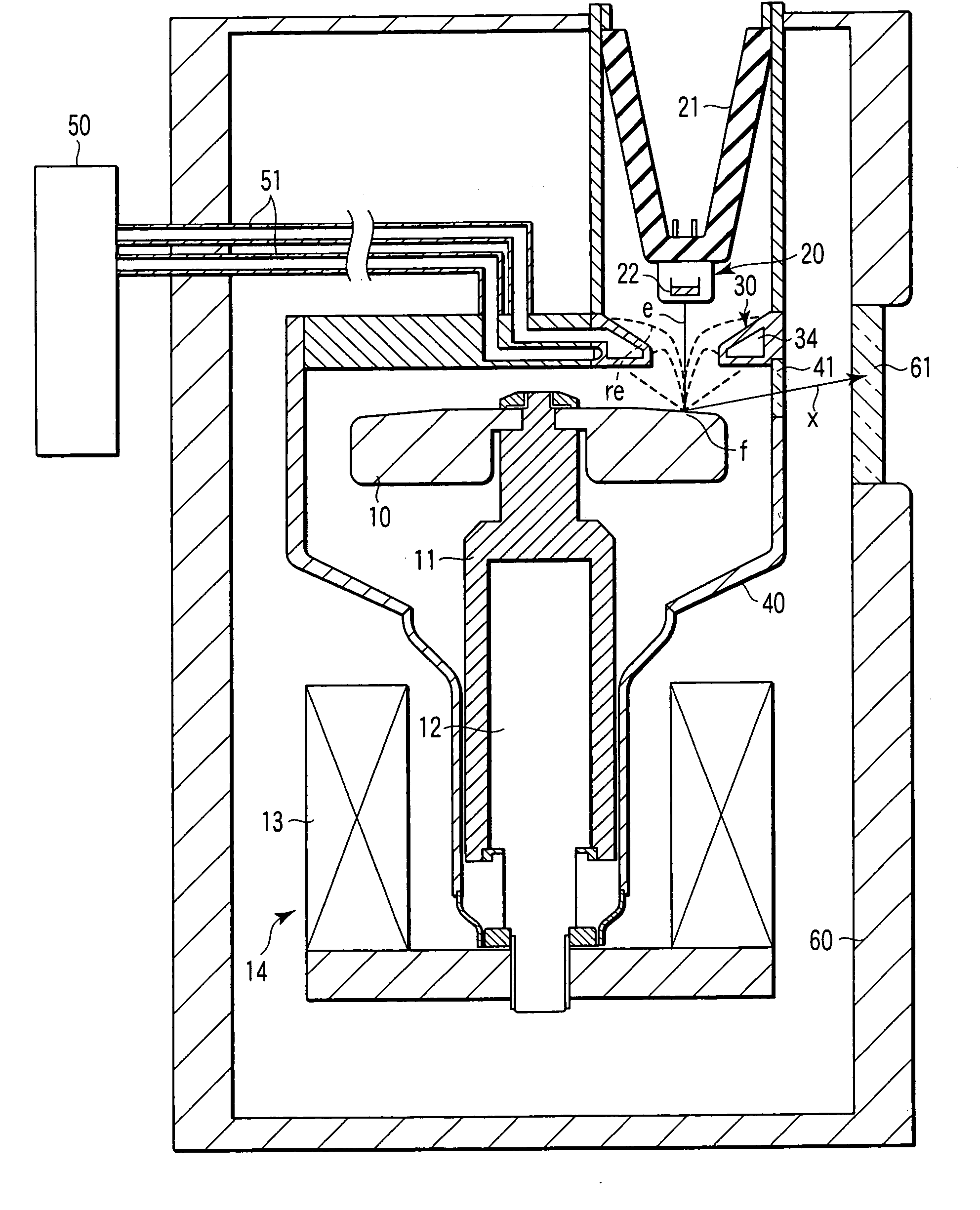
  • Rotation anode X-ray tube
  • Rotation anode X-ray tube
  • Rotation anode X-ray tube

Examples


second embodiment

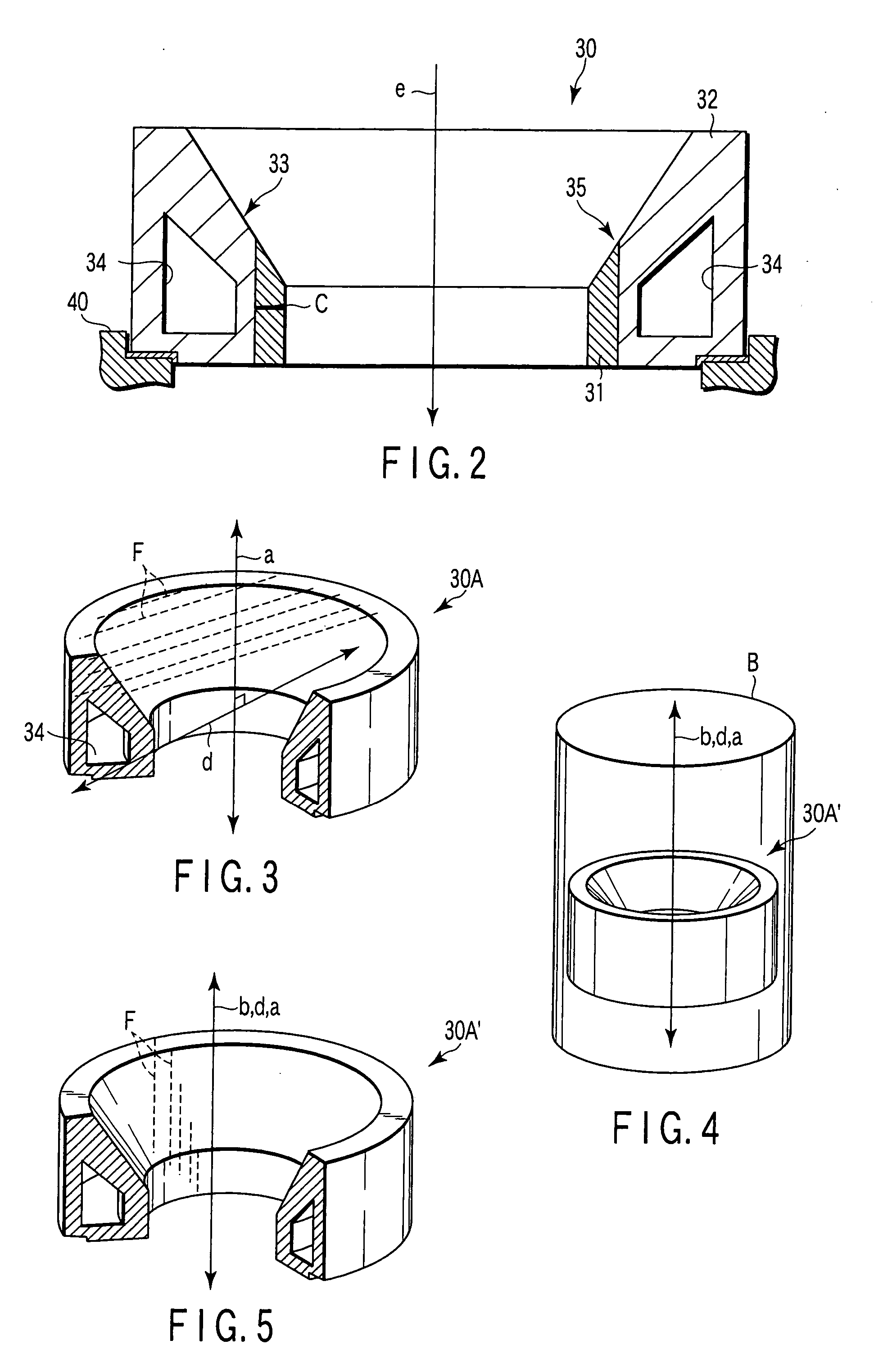
[0060] Next, a second embodiment will be described in detail with reference to FIGS. 3 to 5. FIG. 3 is a partially cutaway perspective view of a recoil electron capturing structure 30A in the second embodiment of the present invention. As shown in FIG. 3, the recoil electron capturing structure 30A in the present embodiment has the same shape as that in the first embodiment, but is entirely made of alumina-dispersed copper.

[0061] Here, characteristics of a conventional recoil electron capturing structure 30A′ will be described. FIG. 4 is an explanatory diagram for explanation of the recoil electron capturing structure 30A in the embodiment, and FIG. 5 is an explanatory diagram for explanation of the recoil electron capturing structure 30A in the embodiment. Note that reference code B in FIG. 4 denotes a bar material prepared by a drawing process or an extrusion process. Further, reference code F in FIG. 5 denotes crystal fibers of alumina-dispersed copper.

[0062] The conventional r...


PUM


Abstract

There are provided an anode target which generates X-rays due to electrons e being incident, an emitter source which emits electrons e to be incident into the anode target, a ring-shaped recoil electron capturing structure which surrounds an orbit of electrons e heading from the emitter source toward the anode target, and captures electrons e emitted from the emitter source and recoiled on the anode target, and a vacuum envelop which keeps at least a periphery of the anode target, the emitter source, and the recoil electron capturing structure at a predetermined degree of vacuum, and the recoil electron capturing structure has a first member formed from strengthened copper which is exposed to the inside of the recoil electron capturing structure, and a second member formed from copper which is disposed at the outside in the radial direction of the first member.

Description

CROSS-REFERENCE TO RELATED APPLICATIONS [0001] This application is based upon and claims the benefit of priority from prior Japanese Patent Application No. 2005-340720, filed Nov. 25, 2005, the entire contents of which are incorporated herein by reference. BACKGROUND OF THE INVENTION [0002] 1. Field of the Invention [0003] The present invention relates to a rotation anode X-ray tube which is mounted on an X-ray image diagnostic system, a nondestructive inspection system, or the like. [0004] 2. Description of the Related Art [0005] A rotation anode X-ray tube which is mounted on an X-ray image diagnostic device, a nondestructive inspection system, or the like, and which is used as a source of release of X-rays has been known. This rotation anode X-ray tube has an anode target which generates X-rays by electron collision, an electron emitting source which emits electrons toward the anode target, and a vacuum envelope which keeps at least the periphery of the anode target and the elect...

Claims


Application Information

Patent Timeline
Patent Type & Authority Applications(United States)
IPC IPC(8): H01J35/12H01J35/10
CPCH01J35/16H01J2235/1204H01J2235/1216H01J2235/1258H01J2235/1262H01J2235/1291H01J2235/168
Inventor SAITO, SHIN
Owner CANON ELECTRON TUBES & DEVICES CO LTD
Learn More