
Gamma vector camera

a gamma vector camera and camera body technology, applied in the field of radiation detection, can solve the problems of limited ability of conventional radiation detection technology, low sensitivity of conventional systems based on pinhole camera designs, and limited sensitivity of conventional systems. achieve the effect of small siz

Active Publication Date: 2010-02-23
LOCKHEED MARTIN CORP
View PDF23 Cites 9 Cited by
  • Summary
  • Abstract
  • Description
  • Claims
  • Application Information

AI Technical Summary

Benefits of technology

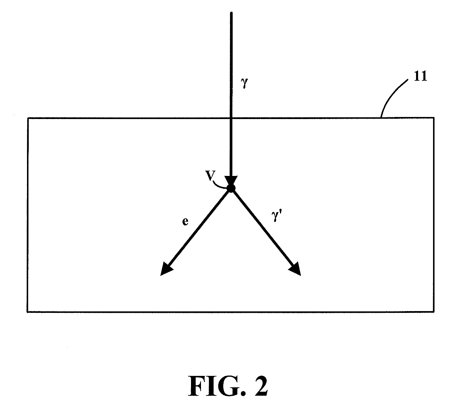
The invention is a gamma vector camera that uses single Compton-scatterings of incident gamma rays to determine the energy spectrum of the gamma ray source and the direction to the source. The camera records the tracks of recoil electrons produced by Compton-scatterings of incident gamma rays and reconstructs them to determine the energies and directions of the recoil electrons. This allows the camera to determine the energy spectrum of the gamma ray source and the direction to the source without requiring multiple events for each incident gamma ray. The camera is smaller in size compared to other gamma ray imaging systems that require either multiple Compton-scatterings of an incident gamma ray or a combination of Compton-scatterings and photo-absorption. The method and computer-readable medium of the invention have the same technical effects as the gamma vector camera.

Problems solved by technology

Conventional radiation detection technologies have significant disadvantages that limit this ability.
For example, conventional systems based on pinhole camera designs have relatively low sensitivity since only a small portion of gamma rays emitted by a gamma ray source pass through the aperture to reach the detector.
Additionally, conventional systems typically have a limited field of view which requires some prior knowledge on the general location of the gamma ray source in order to detect and locate it.
This arrangement strains available resources and is not ideal in areas where a large number of potential carriers are passing through.

Method used


Image

  • Gamma vector camera
  • Gamma vector camera
  • Gamma vector camera

Examples


Embodiment Construction

[0025]The detailed description of the invention set forth below in connection with the associated drawings is intended as a description of various embodiments of the invention and is not intended to represent the only embodiments in which the invention may be practiced. The detailed description includes specific details for the purpose of providing a thorough understanding of the invention. However, it will be apparent to those skilled in the art that the invention may be practiced without all of the specific details contained herein. In some instances, well known structures and components are shown in block diagram form in order to avoid obscuring the concepts of the invention.

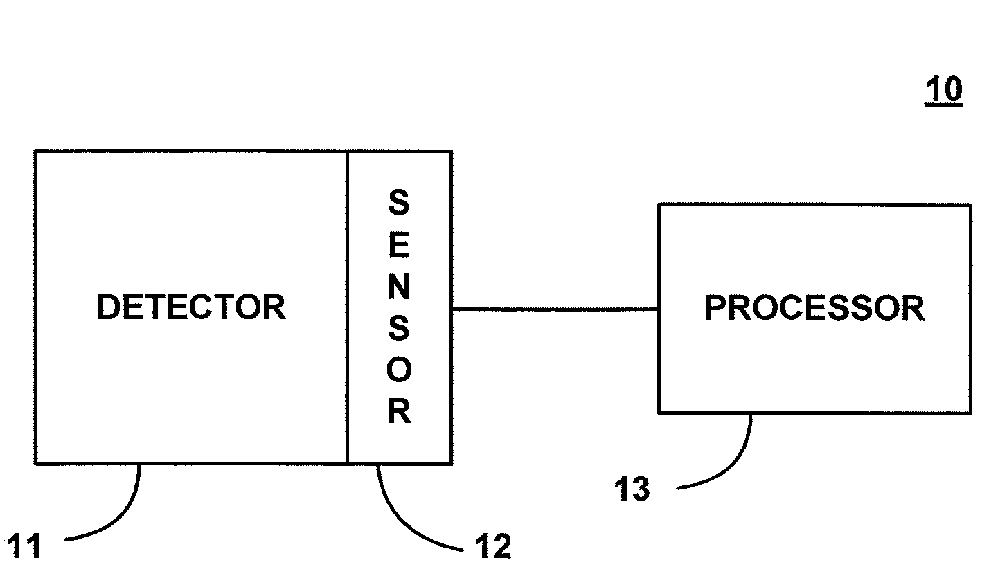
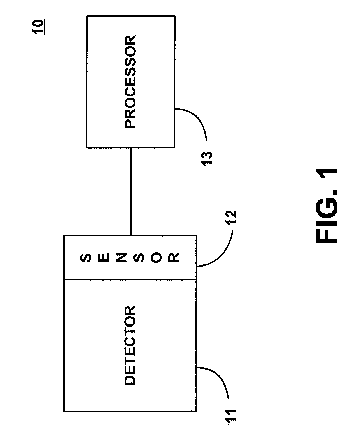
[0026]FIG. 1 is a block diagram depicting basic components of a gamma vector camera according to one embodiment of the invention. As shown in FIG. 1, gamma vector camera 10 includes a detector 11, a sensor 12 and a processor 13. Detector 11 and sensor 12 are part of a detection system configured to detect and...


PUM


Abstract

A gamma vector camera is described for detecting and determining the energy spectrum of a gamma ray source and the direction to the gamma ray source. The gamma vector camera includes a detection system that records a track of a recoil electron produced by a Compton-scattering of an incident gamma ray emitted by the gamma ray source. A processor is configured to determine the energy and the direction of the recoil electron based on the track of the recoil electron recorded by the detection system, and to determine the energy spectrum of the gamma ray source and the direction to the gamma ray source based on the determined energies and directions of a plurality of recoil electrons produced by the Compton-scatterings of a respective plurality of incident gamma rays.

Description

[0001]This application is a continuation-in-part of U.S. application Ser. No. 10 / 866,760 filed on Jun. 15, 2004 now U.S. Pat. No 7,274,020, which claims the benefit of U.S. Provisional Application No. 60 / 484,850 filed on Jul. 3, 2003, both of which are hereby incorporated by reference.STATEMENT AS TO RIGHTS TO INVENTIONS MADE UNDER FEDERALLY SPONSORED RESEARCH OR DEVELOPMENT[0002]The U.S. Government has a paid-up license in this invention and the right in limited circumstances to require the patent owner to license others on reasonable terms.FIELD OF THE INVENTION[0003]The invention generally concerns radiation detection, and more particularly concerns a gamma vector camera for detecting and determining the energy spectrum and the direction to a gamma ray source.BACKGROUND OF THE INVENTION[0004]Radiation detection technology plays a significant role in health and safety applications. These applications include diagnostic systems used for medical imaging or non-destructive testing. S...

Claims


Application Information

Patent Timeline
Patent Type & Authority Patents(United States)
IPC IPC(8): G01T1/20G01T1/24
CPCG01T1/1642G01T1/201
Inventor HINDI, MUNTHER M.KLYNN, LEE M.DEMROFF, HOWARD P.
Owner LOCKHEED MARTIN CORP
Learn More