
Method of manufacturing multilayer metal wire or ribbon bandage over operational zone of rotor

Active Publication Date: 2015-09-08
PULNIKOV SERGEY
View PDF4 Cites 12 Cited by
  • Summary
  • Abstract
  • Description
  • Claims
  • Application Information

AI Technical Summary

Benefits of technology

The patent text discusses the use of a permeable bandage to reduce magnetic field pulsations in electrical machines, which can improve their performance and efficiency. The bandage can be used in both stators and rotors, and can help reduce torque ripples, noise, and magnetic losses. Additionally, the bandage can prevent magnetic leakage by selecting materials with reduced saturation flux density or integrating non-magnetic wires into the bandage.

Problems solved by technology

The magnetic field created by the stator is not smooth and uniform because of the slotted structure.
However this is not always practical, because of the difficulty of putting a stator winding in closed slots.
Rotors can also have a slotted structure and thus have the same problem with pulsations of magnetic field generated by such rotors.
In addition to that magnets are often installed with a gap between them, which causes a local drop in magnetic field.
Pulsations of magnetic field in the air-gap adversely affect operation of electrical machines by causing additional magnetic losses, torque ripples and noise.
The overall efficiency and performance of such machines is therefore reduced.

Method used


Image

  • Method of manufacturing multilayer metal wire or ribbon bandage over operational zone of rotor
  • Method of manufacturing multilayer metal wire or ribbon bandage over operational zone of rotor
  • Method of manufacturing multilayer metal wire or ribbon bandage over operational zone of rotor

Examples


Embodiment Construction

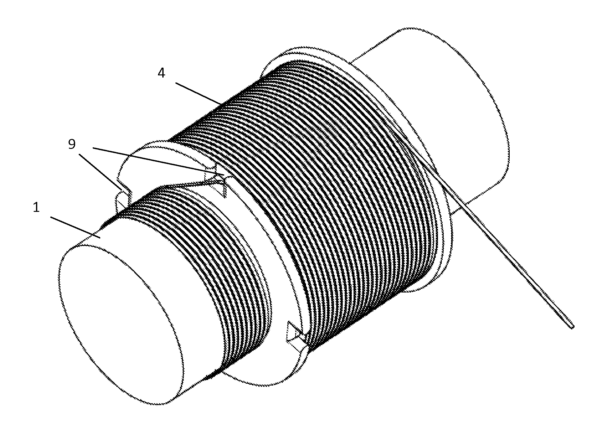
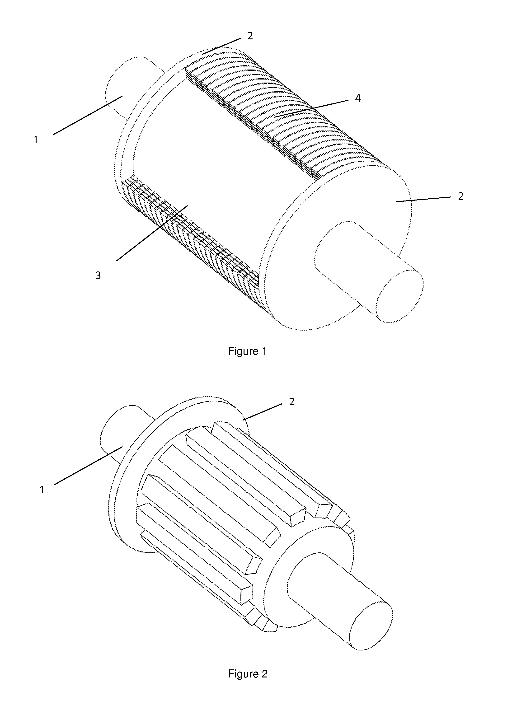
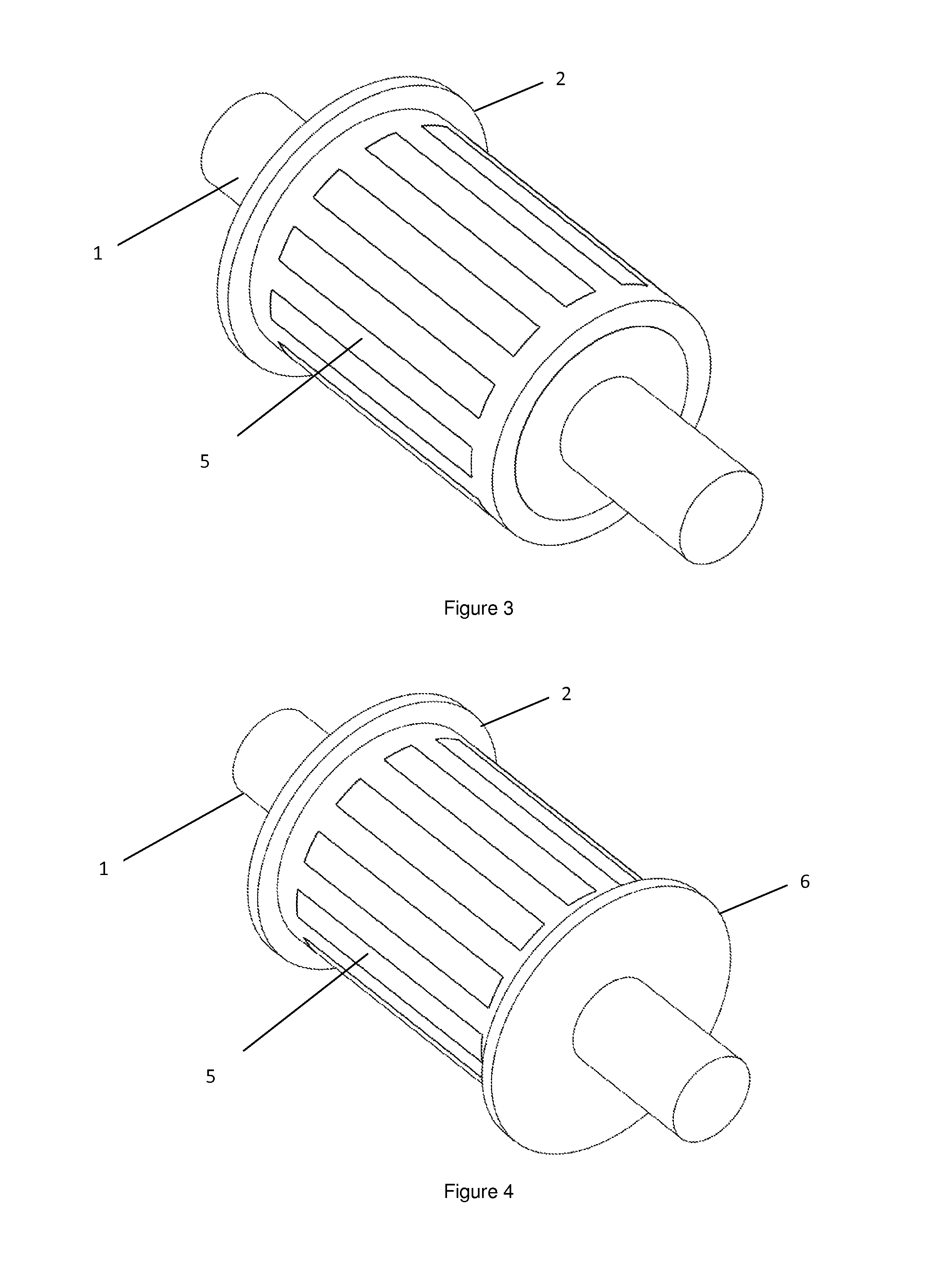
[0033]A general rotor structure with a steel wire bandage is shown in FIG. 1. Here only the active part of the rotor (1) is considered. The active part is restricted by two side rings (2). This is necessary in order to stabilize the sides of the steel wire bandage. The side rings do not have to be solid, but are allowed to contain slots or holes, if this is necessary for operation or for manufacturing purposes. The operational area for the bandage is indicated by (3). Although the operational area is expected to be cylindrical, some minor deviations could be permitted. This however would also depend on the type and especially conformity of the wire used for the winding. The bandage itself is denoted by (4). It can be shown that practically any rotor could be adjusted in order to fit the basic requirements of the proposed technology. Some of such adjustments will be presented. However it does not have to be concluded that the proposed technique is restricted to the considered rotor s...


PUM

PropertyMeasurementUnit
Temperatureaaaaaaaaaa
Pressureaaaaaaaaaa
Angleaaaaaaaaaa

Abstract

A manufacturing method for permeable bandages and magnetic cores for rotors of electrical machines is proposed. The proposed method relies on winding with insulated metal preferably permeable wire or ribbon with high pretension and maintaining pretension in the wire or ribbon during manufacturing steps. The proposed method could be especially useful for high-speed electrical machines.

Description

1. BACKGROUND OF THE INVENTION[0001]This invention is related to permeable bandages and magnetic cores for rotors of rotating electrical machines. The proposed method could be especially useful for high-speed electrical machines.[0002]The proposed method could be used for containment of permanent magnets, for containment of magnetic cores with permanent magnets, for containment of metal squirrel cages of high speed induction machines, for containment of electrical windings installed in the slots of the rotor, for closing rotor slots or even as a mean of assembly of complex rotors consisting of separate parts or sectors through compressing and containing these parts or sectors against a shaft.[0003]Permanent magnets located on rotors of electrical machines often require containment sleeves. Such containment sleeves can be performed out of metal as described in US 2008 / 0238234 A1 and U.S. Pat. No. 7,042,118. Solid sleeves provide a path for eddy currents, which increases the rotor tem...

Claims


Application Information

Patent Timeline
IPC IPC(8): H02K1/27H02K15/12H02K15/03H02K17/16H02K15/00H02K15/02H02K1/28H02K3/51H02K3/46H02K3/48
CPCH02K15/02H02K15/0012H02K15/12H02K15/03H02K17/165H02K1/28H02K1/278H02K3/48H02K1/2706H02K3/46H02K3/51Y10T29/49012H02K17/168
Inventor PULNIKOV, SERGEY
Owner PULNIKOV SERGEY
Learn More