

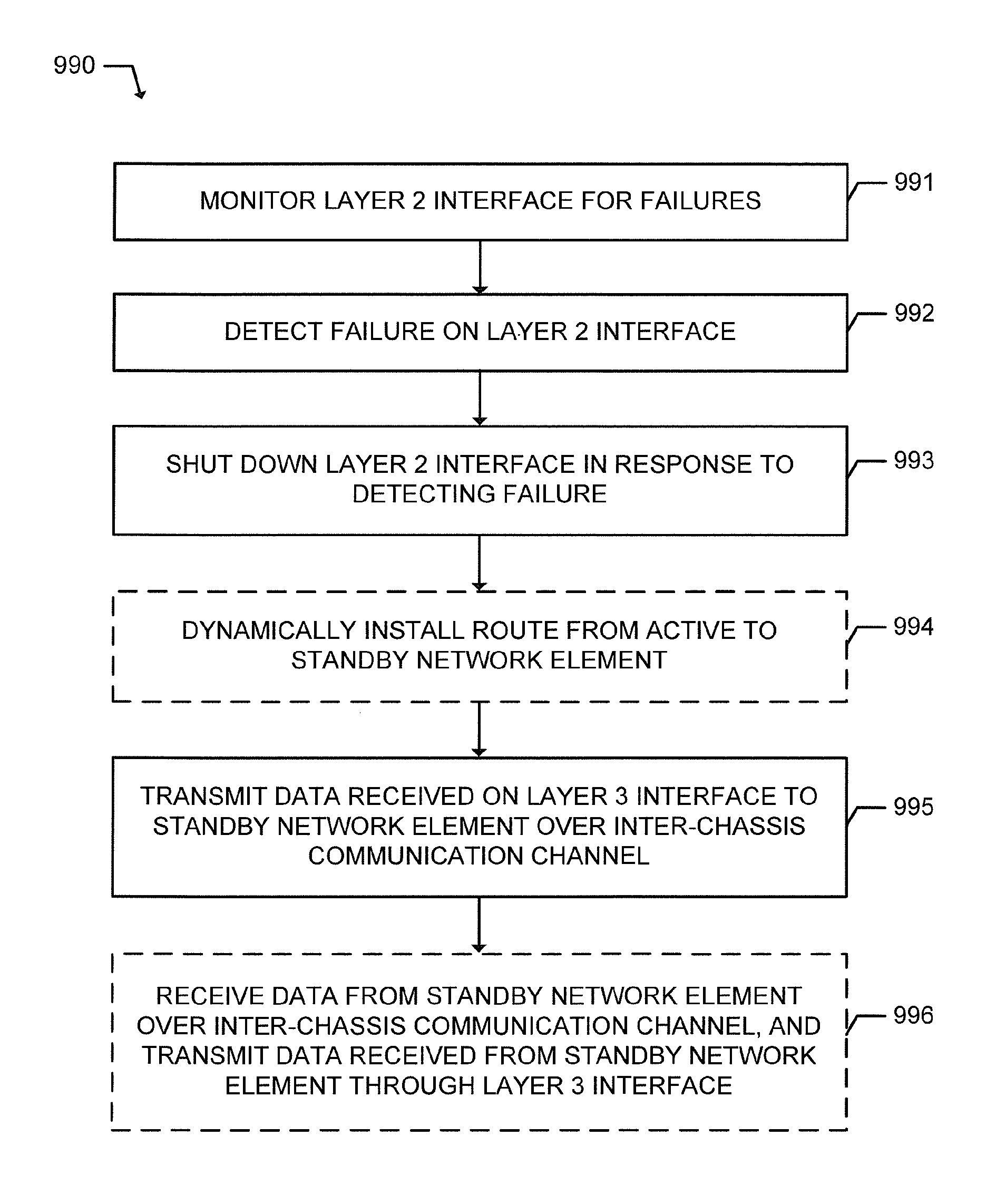
Method and network element to limit service disruption due to a failure on a layer 2 interface
a layer 2 interface and failure technology, applied in the field of network communication, can solve the problems of conventional icr system may not provide sufficient protection against service outages and/or loss of network traffic, so as to limit the disruption of session handling, and limit the effect of session handling
- Summary
- Abstract
- Description
- Claims
- Application Information
AI Technical Summary
Benefits of technology
Problems solved by technology
Method used
Image

Examples
Embodiment Construction
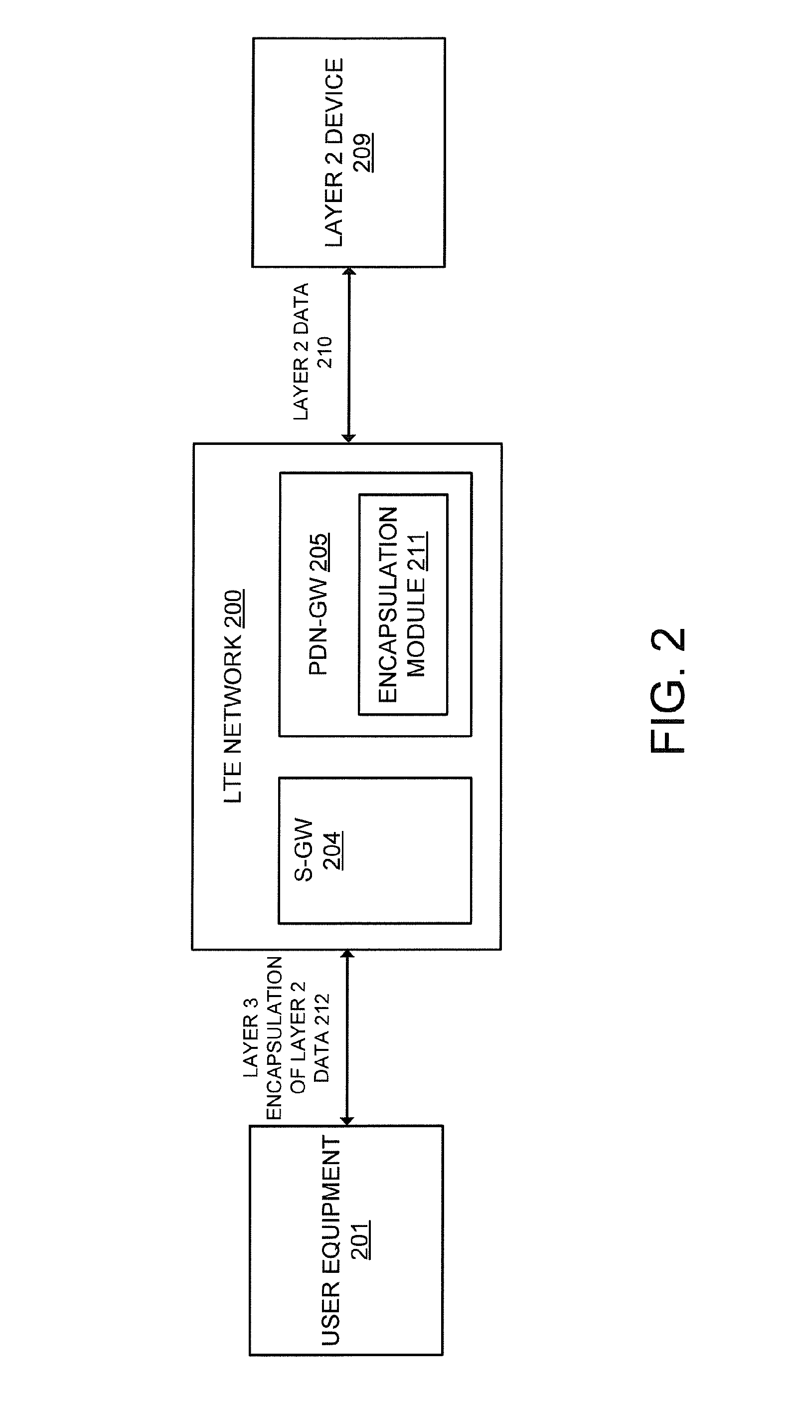
[0023]As mentioned in the background section, when Layer 2 data is transmitted through the LTE network, the conventional ICR system may not provide sufficient protection against service outages and / or loss of network traffic. The current ICR system used in the PDN-GW and / or the network element performing the Layer 3 encapsulation of the Layer 2 data is not conventionally operable to monitor and detect failures on a Layer 2 interface. Following a failure on the Layer 2 interface, the network may detect the failure and begin to forward downlink traffic to the Layer 2 interface of the standby network element instead of to the active network element having the failed Layer 2 interface. However, uplink traffic may still be received on the Layer 3 interface of the active network element. This may lead to the uplink packets being dropped at the active network element as a result of the failure on the Layer 2 interface. Additionally, the standby network element may not be fully ready to ass...
PUM
 Abstract
Description
Claims
Application Information