
Fire-retarding device on storage tanks

a technology for storage tanks and fire-retarding devices, which is applied in boring tools, medical science, dentistry, etc., can solve the problems of insufficient delay of flame ignition, inability to stop the ignition of almost explosive flames in most cases, and stretched material formed of irregular fibers, etc., to achieve the effect of effective delay of flame ignition

Active Publication Date: 2015-09-15
VSAT SATELLITENKOMMUNIKATION
View PDF16 Cites 0 Cited by
  • Summary
  • Abstract
  • Description
  • Claims
  • Application Information

AI Technical Summary

Benefits of technology

The invention aims to create a device that delays the ignition of flames until emergency measures can be initiated at any filling level. This is achieved by using cover bodies made of stretched material that rest on the surface of the liquid and contain PU foam inside them. This foam acts as a floating agent, effectively delaying the rapid ignition of flames at the beginning of a fire. It is advantageous if the foam is applied in toroidal form and the cover bodies are made of stretched material and arranged closely lined-up in the tank to ensure no or the fewest possible gaps remain between them.

Problems solved by technology

It is known to discover or reduce a spreading of the fire through alarm devices and local fire protection devices, but this is not sufficient to delay the ignition of flames in large tanks.
Provisions are made such as solid covers for oxygen deprivation, containment of the development of heat and the like, but the almost explosive ignition of flames cannot be stopped in most cases, in particular if the filling level of roofed tanks sinks so far that the ambient air promotes the fire or the collecting chamber surrounding the tank starts to fill through leakage.
It is, however, disadvantageous that with the line-up, gaps form that cannot delay the igniting fire, and the remedy must be evaluated as modest.
This stretched material formed of irregular fibers is, however, not suited to reduce the risk of a fire, since a homogeneous covering is not present on account of outside influences, e.g., wind or the like.

Method used


Image

  • Fire-retarding device on storage tanks
  • Fire-retarding device on storage tanks
  • Fire-retarding device on storage tanks

Examples


Embodiment Construction

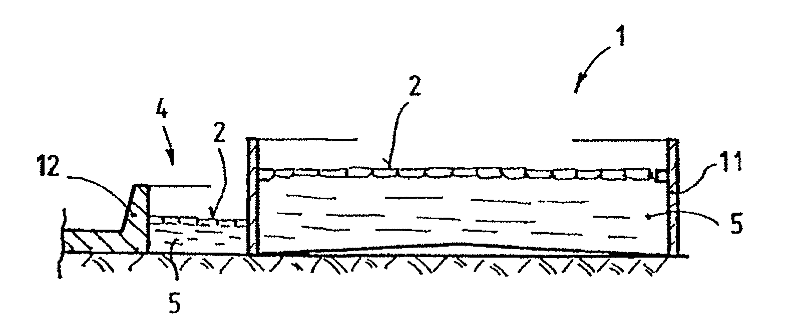
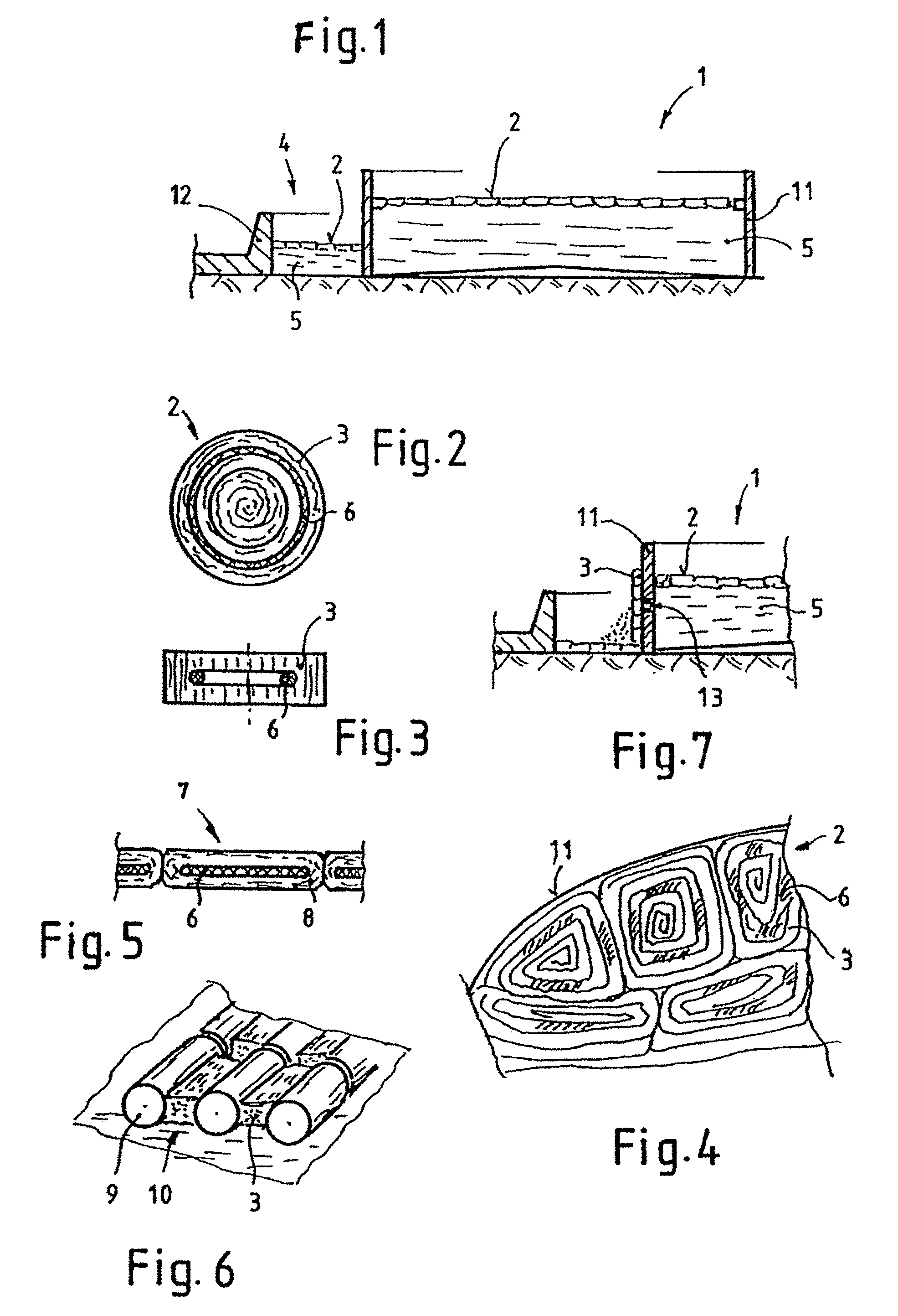
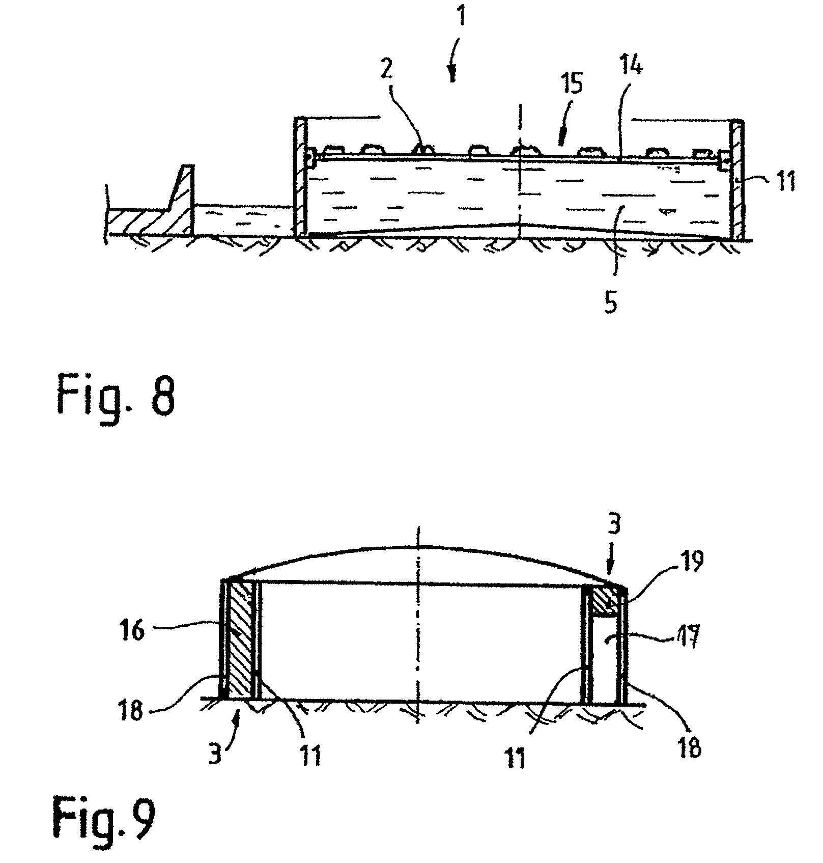
[0029]FIG. 1 shows in section an installation for receiving combustible liquid media, such as crude oil or the like. The tank 1, which comprises a cylindrically arranged side wall 11 connected tightly to the floor in a fixed manner, is filled with crude oil 5. Floating covers, so-called cover bodies 2, are laid on the surface of the liquid 5, which cover bodies are connected to one another in a jointless manner. Outside the tank 1 a collecting chamber 4 is provided which serves to receive any leaked liquid 5 and is delimited by the ring barrier 12. The collecting chamber 4 is dimensioned such that it can receive the amount of liquid until level equalization.

[0030]FIG. 2 shows a cover body 2 comprising stretched material 3 with one or more layers. The stretched material 3 is built from a metal band which contains a plurality of small lengthwise, staggered cuts and forms bridges by lateral stretching. This stretched material 3 is now processed into a roll first of all. PU foam 6 is no...


PUM


Abstract

Device for reducing the risk of fire or delaying the ignition of flames in preferably large open or roofed storage tanks for combustible liquid media covered by floats, such as crude oil or the like, comprising a fixed cylindrical cavity as a tank for receiving the liquid, which tank is provided with a further protective barrier surrounding it at a certain distance and serving as a collecting chamber in case of leakage. The device is characterized in that the tank, if applicable the collecting chamber, contains floating cover bodies made of rolled-up stretched material that rest in a fined-up manner floating on the surface of the liquid, whereby polyurethane foam is inserted into the interior of the cover bodies, serving as a floating agent.

Description

BACKGROUND OF THE INVENTION[0001]1. Field of the Invention[0002]The invention relates to a device for reducing the risk of fire or delaying the ignition of flames in preferably large open or roofed storage tanks for combustible liquid media covered by floats, such as crude oil or the like, comprising a fixed cylindrical cavity as a tank for receiving the liquid, which tank is optionally provided with a further protective barrier surrounding it at a certain distance and serving as a collecting chamber in case of leakage.[0003]2. Background Information[0004]In case of afire, this device serves to delay the spreading until countermeasures can be taken or it is possible to make fire-fighting provisions. This is of particular importance, since valuable time passes before the discovery of a fire and the arrival of fire fighting vehicles.[0005]It is known to discover or reduce a spreading of the fire through alarm devices and local fire protection devices, but this is not sufficient to del...

Claims


Application Information

Patent Timeline
IPC IPC(8): A62C2/06A62C2/10A62C3/00A62C3/06
CPCA62C3/06A62C2/06A62C2/065A62C2/10A62C3/002
Inventor STUHLBACHER, FRANZKRAICZAR, MARKUS
Owner VSAT SATELLITENKOMMUNIKATION
Learn More