Axial shaft seal for a turbomachine

a technology of axial shaft and seal, which is applied in the direction of leakage prevention, motors, liquid fuel engines, etc., can solve the problems of increasing wear or even damage to the turbomachine, the seal on the shaft requires a long length, and the leakage loss can not be prevented. , to achieve the effect of preventing leakage losses

Active Publication Date: 2015-09-15
ATLAS COPCO ENERGAS
View PDF14 Cites 12 Cited by
  • Summary
  • Abstract
  • Description
  • Claims
  • Application Information

AI Technical Summary

Benefits of technology

[0008]Another object is the provision of an improved shaft seal for a turbomachine that overcomes the above-given disadvantages, in particular that avoids or at least reduces the above-described disadvantages.SUMMARY OF THE INVENTION
[0010]Thus the entire seal assembly with its seals for maintaining the pressure differential between the radial flow region and the axial space is provided in the radially extending gap and an axially extending section of the rotor shaft is free of seals. Accordingly, the shaft does not have to be long enough to accommodate a seal, enabling the rotor shaft to be made correspondingly shorter. The dynamic rotational behavior of the rotor is significantly improved even though the saving in material and space is relatively small. By shortening the axial installation space of the rotor shaft, the whole rotor becomes stiffer, as a result of which the specific natural vibration frequencies are increased. Accordingly, when operating the turbomachine, the specific natural frequencies are only reached at extremely high speeds, even when they cannot actually be shifted above the maximum speed.
[0016]Depending on the process fluid, it may be necessary to protect the fluid against contamination or to prevent leakage losses escaping from the process fluid into the housing. In order to flush the region of the seal assembly or to discharge a leakage gas, a connecting opening for feeding in a blocking gas or for discharging the leakage gas can be provided in at least one intermediate chamber formed between the seals. This intermediate chamber also extends at least in sections along the gap in a radial direction. The connecting opening can be formed by a hole in the housing, for example, to which a feed or discharge pipe leading to a pump is connected.

Problems solved by technology

Accommodating all this structure—electric machine, bearings, seals—on the shaft requires it to be quite long.
Due to the high rotational speeds, the problem frequently arises when operating turbomachines that the natural frequency of the components, in particular of the rotor assembly, must be taken into account.
When the operating frequency in the turbomachine lies in the region of critical natural frequencies, there is a risk of increased vibration that can lead to increased wear or even to damage to the turbomachine.

Method used


Image

  • Axial shaft seal for a turbomachine
  • Axial shaft seal for a turbomachine
  • Axial shaft seal for a turbomachine

Examples


Embodiment Construction

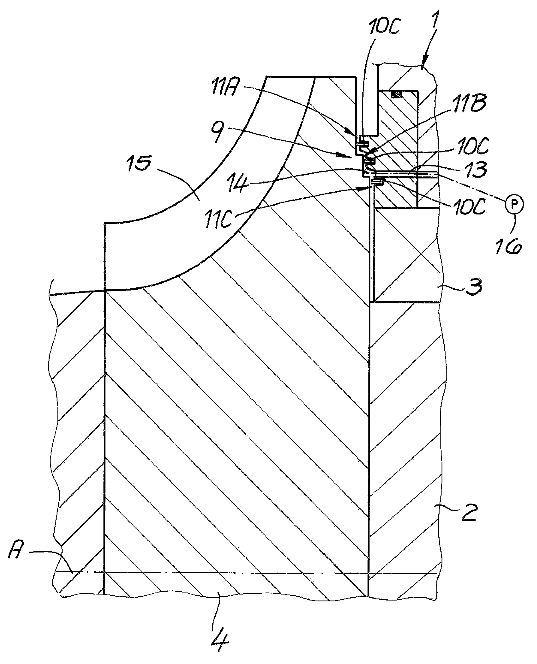
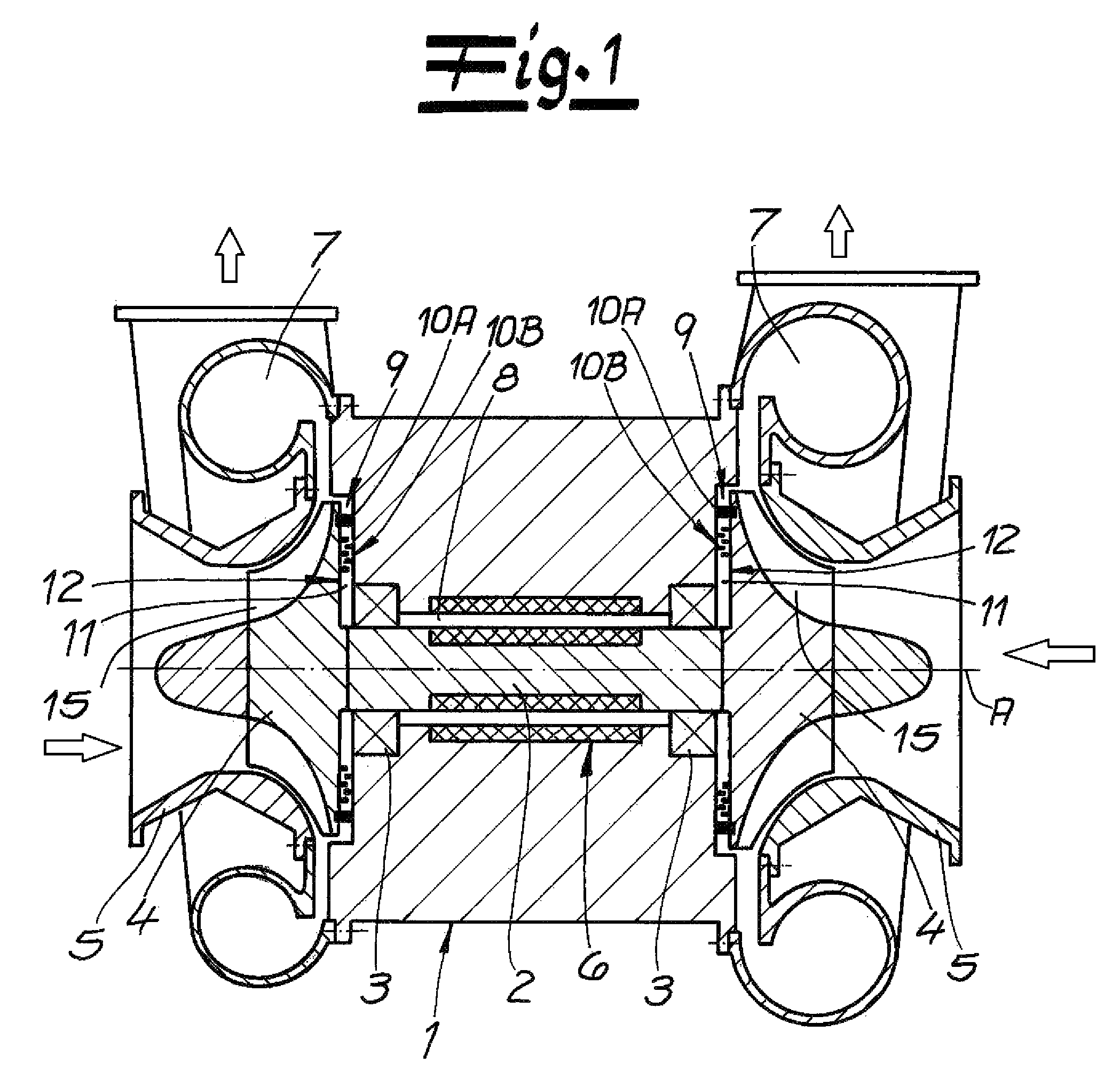
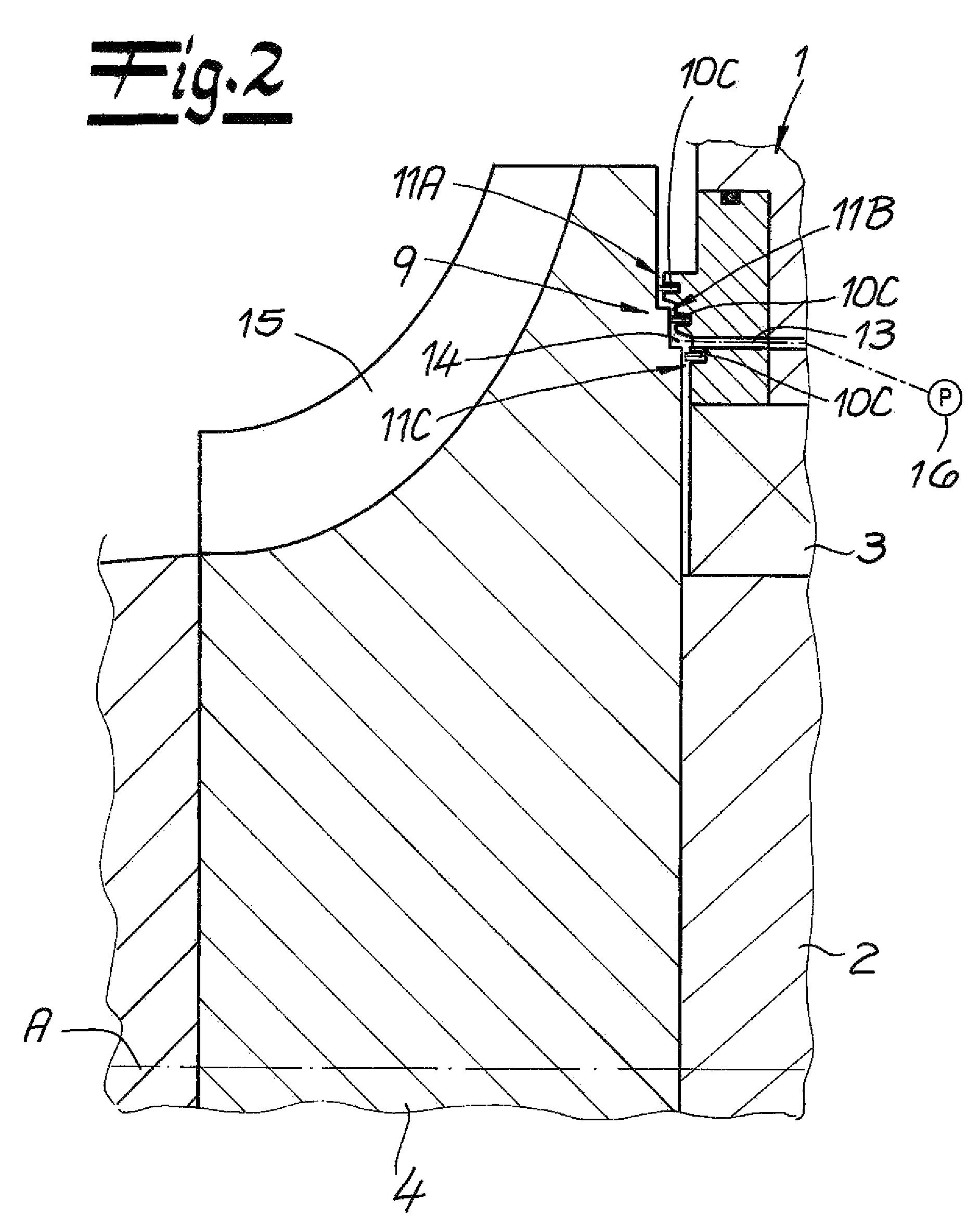
[0021]As seen in FIG. 1 a turbomachine has a rotor shaft 2 extending along an axis A in a passage of a housing 1. Axial- and radial-thrust bearings 3 for the rotor shaft 2 can be roller bearings, magnetic bearings, hydrostatically lubricated bearings and / or hydrodynamically lubricated bearings. A cylindrical outer surface of the shaft 2 forms with a cylindrical inner surface of the housing 1 an annular and axially extending gap 8.

[0022]In the illustrated embodiment, a cantilevered radial impeller 4 is carried on each end of the rotor shaft 2 in a respective impeller housing 5 and forms therewith a respective flow region 7 through which a fluid, typically air, flows radially outward by axially outwardly and radially extending vanes 15 on the impellers 4. This air flow is either forced axially inward and expelled radially outward when the turbomachine is being operated as an expander or sucked axially inward and expelled radially outward when the turbomachine is operated as a compress...


PUM


Abstract

A turbomachine has a housing having a passage extending along an axis and an annular axially directed housing face extending radially from the passage. A shaft extending axially in the passage has an outer shaft surface radially spaced from an inner surface of the passage and forming therewith an annular axially extending gap. A radial impeller fixed to the shaft outside the housing has an axially directed and radially extending impeller face axially spaced from and confronting the radial housing face and forming therewith a radially extending gap opening into the axially extending gap. An impeller housing forms a flow space with the impeller outside the housing. The radial gap opens into the flow space. A plurality of spaced seals engaged in the radial gap between the radial faces of the housing and impeller fluidically separates the axial gap from the flow space.

Description

FIELD OF THE INVENTION[0001]The present invention relates to an axial shaft seal. More particularly this invention concerns such a seal for a turbomachine.BACKGROUND OF THE INVENTION[0002]A standard turbomachine has a rotor shaft mounted in a housing, at least one radial impeller arranged on an end of the rotor shaft in a respective impeller housing and having a seal assembly between a flow region of the impeller housing and a free space surrounding the rotor shaft inside the housing. The seal assembly in turn has a plurality of seals spaced apart from one another in order to separate the flow region from the free space. The radial impeller serves to expand or compress a fluid so that the flow regions inside the impeller housing, in particular a flow region radially adjacent the impeller, are at a pressure different from that of the rotor shaft inside the free space surrounding the housing, typically higher.[0003]In order to avoid unwanted fluid flow through the housing and to avoid...

Claims


Application Information

Patent Timeline
Patent Type & Authority Patents(United States)
IPC IPC(8): F01D11/02
CPCF01D11/02F04D29/083F16J15/16
Inventor WIEBE, FRANK
Owner ATLAS COPCO ENERGAS
Why Eureka
Try Eureka