Linear motion guide unit

a technology of motion guide unit and guide rod, which is applied in the direction of linear bearings, shafts and bearings, bearings, etc., can solve the problems of poor lubrication, insufficient supply of lubricant, and insufficient volume of sleeves, so as to increase the number of parts

Active Publication Date: 2015-09-15
NIPPON THOMPSON
View PDF10 Cites 0 Cited by
  • Summary
  • Abstract
  • Description
  • Claims
  • Application Information

AI Technical Summary

Benefits of technology

[0015]With the linear motion guide unit constructed as stated earlier, the end cap has slits cut in the outside circular wall surface of the turnaround passage defined in the end cap, while the applicator nose of the lubricant reservoir plate of porous compact impregnated with the lubricant lying in the concavity of the end cap is exposed itself through the slits to the turnaround passage to come into engagement with the rolling element to make application of lubricant around the rolling element while rolling through the turnaround passage. The lubricant reservoir plate is supplied with lubricant from the lubricant-containing member which is packed in the compartments formed in the end cap. The lubricant-containing member is resupplied with lubricant by means of a lubricant syringe through oiling holes on the wall of the end cap and in doing so lubrication around the rolling element is carried out without interruption. Especially, as the lubricant-containing member is separately placed in many compartments defined with the reinforcing ribs in the end cap, the empty space in the end cap may be available effectively to stow many blocks of the lubricant-containing member to retain a plenty of lubricant. Moreover, as many oiling holes are made on the upper surface and / or side surfaces of the end cap major body, lubricant is resupplied easily into the inside space of the end cap major body through the oiling holes by use of the lubricant syringe through oiling holes on the wall of the end cap to impregnate the lubricant-containing member with much lubricant. As a result, the smooth application of lubricant around the rolling element is carried out to make it possible to lubricate the rolling element for a prolonged period of time.
[0016]While the rolling element rolls through the turnaround passage, Lubricant is applied to the rolling element through the slits made in the inside circular surface of the turnaround passage. This lubricating system of the present invention is preferable to realize the maintenance-free for lubrication with no need of the provision of separate lubricating member and the increase of number of parts. Moreover, the rolling element experiences any inertia or centrifugal force while the rolling direction changes from the linear race or return passage to the curved turnaround passage. Thus, the rolling element while rolling through the turnaround passage is suffered to the centrifugal force or linear thrust to come into engagement with the circular surface of the turnaround passage whereby lubricant is securely applied to the rolling element while rolling through the turnaround passage. With the linear motion guide unit constructed as stated earlier, the rolling element is applied with lubricant while rolling through the turnaround passage to realize maintenance-free lubrication for the rolling element. According to the present invention, there is no need of enlargement in diameter of the hole or opening to add parts or components for lubrication as in the conventional art. This means the linear motion guide unit is kept safer than ever in stiffness or rigidity against external load.

Problems solved by technology

Meanwhile, though the conventional linear motion guide units have been expected to continue application of lubricant around the rolling elements over a prolonged interval of time to realize the maintenance-free working for lubrication, there has been ever developed no lubricant supplier means good enough to continue supplying lubricant around the rolling elements over a prolonged interval of time to realize the maintenance-free working for lubrication.
However, the sleeve construction, as very thin in thickness, becomes too less in volume to keep sufficient amount of lubricant.
Thus, there is a fear of poor lubrication such as binding between rolling elements or sticky condition which would be caused by lubrication lack around the rolling elements.
Moreover, although there is provided the linear motion guide unit of roller type in which porous compact impregnated with lubricant fits into the end cap and applicator noses extend to expose themselves to the turnaround passages to carry out application of the lubricant around rolling elements from the inside circular surfaces of the turnaround passages while rollers roll across the turnaround passage, the linear motion guide unit constructed as stated just earlier has a major problem that the structure becomes very sophisticated.
With the linear motion guide unit of such type that the lubricating member makes contact with the raceway surface of the guide rail, there is a major challenge that the lubricating member suffers with much frictional resistance because of resupply of lubricant and correspondingly is worn down to gradually change in contact condition, causing poor lubricating condition.
As a result, there will be fear of a serious issue that the lubricant-containing polymer suffers more shrinkage than the reinforcing member with the result that the supply of the lubricating agent around the rolling elements is hindered.

Method used


Image

  • Linear motion guide unit
  • Linear motion guide unit
  • Linear motion guide unit

Examples


Embodiment Construction

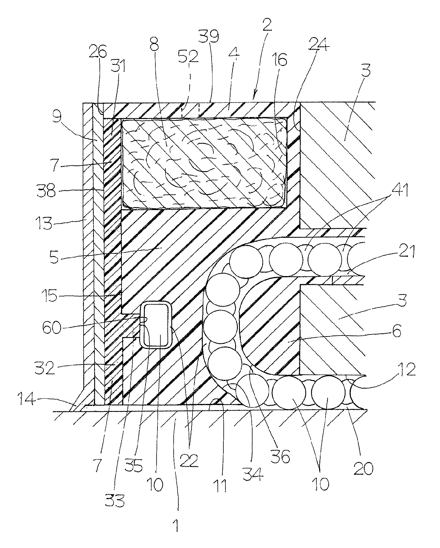
[0031]The linear motion guide unit of the present invention is adapted for use in any relatively sliding components in machinery as diverse as semiconductor fabricating equipment, precision machines, measurement / inspection instruments, medical instruments, robotic machines, various assembling machines, micromachines, and so on. Especially, the present invention is intended to develop the linear motion guide unit in which the lubricating member is resupplied with lubricant to continue application of lubricant around the rolling elements over a prolonged interval of time. A preferred embodiment of the linear motion guide unit constructed according to the present invention will be described in detail by reference to the drawings.

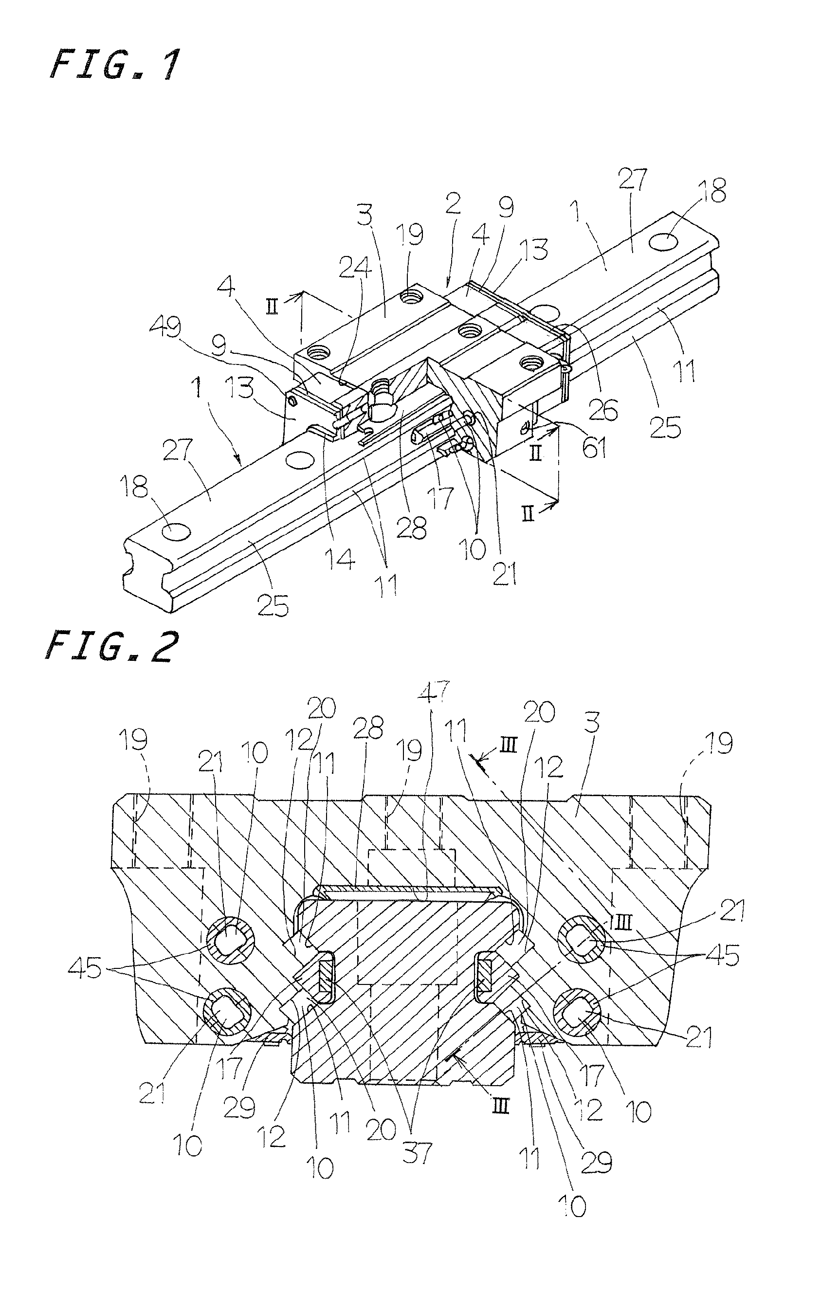
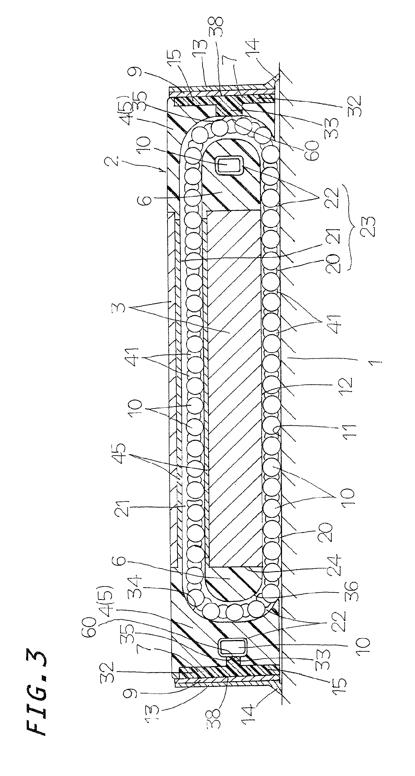
[0032]The linear motion guide unit of the present invention, as shown in FIGS. 1 to 3, is in general composed of an elongated guide rail 1 and a slider 2 which fits over or conforms to the guide rail 1 so as to move relative to the guide rail 1 through more tha...


PUM

PropertyMeasurementUnit
shapeaaaaaaaaaa
molecular weightaaaaaaaaaa
pressureaaaaaaaaaa

Abstract

A lubricating member is composed of a lubricant reservoir plate of a porous compact and a lubricant-containing member of fibrous material. The lubricating member is packed in an empty space in the end cap to make sure of maintenance-free operation for lubrication over a prolonged period of time. The lubricant reservoir plate is stowed in a recess formed on an outward end surface of the end cap major body and the lubricant-containing member is placed in the space lying deeper than the recess. A packing plate is placed between the lubricant reservoir plate and the lubricant-containing member with making close engagement with an edge defining the recess on the end cap to cover entirely a whole area of the lubricant reservoir plate to seal the lubricant impregnated in the lubricant reservoir plate inside the end cap.

Description

FIELD OF THE INVENTION[0001]The present invention relates to a linear motion guide unit composed of an elongated guide rail and a slider designed to move on the elongated guide rail relative to the guide rail through more than one rolling element. More especially, the present invention relates to a linear motion guide unit in which the slider has therein a porous compact able to be replenished or resupplied with lubricant.BACKGROUND OF THE INVENTION[0002]With the conventional linear motion guide units of roller type, lubrication members are installed in the end caps lying at opposite ends in the sliding direction of the slider to apply lubricant around the rolling elements inside the turnaround passages in the end caps, thereby to accomplish maintenance-free operation for lubrication. In Japanese Laid-Open Patent Application No. 2007-100 951 which is a commonly-assigned senior application, for example, there is disclosed a linear motion guide unit having lubricant resupply means in ...

Claims


Application Information

Patent Timeline
Patent Type & Authority Patents(United States)
IPC IPC(8): F16C29/06F16C33/66
CPCF16C33/6648F16C29/0633F16C33/6655F16C29/0609F16C29/065F16C33/6659F16C2322/59
Inventor KITO, KUNIHIKO
Owner NIPPON THOMPSON
Why Eureka
Try Eureka