Apparatus and methods for fiber integration and registration

a technology of fiber integration and registration, applied in the direction of instruments, catheters, force measurement by measuring optical property variation, etc., can solve the problems of affecting the performance of the catheter, affecting the accuracy of the shape algorithm, and limited utility of elongating medical instrument applications,

Active Publication Date: 2015-09-22
AURIS HEALTH INC
View PDF142 Cites 52 Cited by
  • Summary
  • Abstract
  • Description
  • Claims
  • Application Information

AI Technical Summary

Benefits of technology

[0014]In certain variations, a method of actuating an elongate instrument may include one or more of the following steps. A system may be operatively coupled to a controller. The system may include an elongate instrument; a housing coupled to a proximal portion of the elongate instrument, where the housing comprises an interface for receiving an actuating force and transferring the actuating force to the elongate instrument to articulate a distal portion of the elongate instrument; and a shape sensing fiber. The elongate instrument may have a proximal end, a distal end and at least one lumen defined therein. At least a first portion of the fiber may be positioned within the lumen of the elongate instrument, and a second portion of the fiber may be positioned within the housing. The second portion of the fiber may include a service loop. Actuating motion may be transferred from the controller to the system to articulate the distal portion of the elongate instrument in at least one degree of freedom, where the service loop allows the fiber to slide or be displaced within the lumen of the elongate instrument when the distal portion of the elongate instrument is articulated, thereby controlling the amount of strain the fiber is subjected to and maintaining shape sensing properties of the fiber.
[0016]In certain variations, a method of actuating an elongate instrument may include one or more of the following steps. An assembly may be operatively coupled to a controller. The assembly may include an elongate instrument; a housing coupled to a proximal portion of the elongate instrument, wherein the housing comprises an interface for receiving an actuating force and transferring the actuating force to the elongate instrument to articulate a distal portion of the elongate instrument; and a shape sensing fiber. At least a first portion of the fiber may be positioned in the lumen of the elongate instrument. At least a second portion of the fiber may be positioned in the housing such that the coordinate system of the fiber can be matched to the coordinate system of the elongate instrument to register the fiber to the elongate instrument. The second portion of the fiber may include a service loop. Actuation motion may be transferred from the controller to the assembly to articulate the distal end of the elongate instrument in at least one degree of freedom. The service loop may allow the fiber to slide or displace within the lumen of the elongate instrument when the distal portion of the elongate instrument is articulated, thereby controlling the amount of strain the fiber is subjected to. Saved registration data regarding registration between the coordinate system of the fiber and the coordinate system of the elongate instrument may be accessed from a memory component to determine the shape of the elongate instrument.

Problems solved by technology

Conventional technologies such as electromagnetic position sensors may be utilized to measure 3-dimensional spatial position but may be limited in utility for elongate medical instrument applications due to hardware geometric constraints, electromagnetivity issues, etc.
However, large strain changes induced by mechanical structures (such as pinching, twisting, etc.) may disrupt the accuracy of shape algorithms.
The addition of components to a catheter may negatively affect the performance of a catheter (such as stiffness, inner and outer diameters, etc.).

Method used


Image

  • Apparatus and methods for fiber integration and registration
  • Apparatus and methods for fiber integration and registration
  • Apparatus and methods for fiber integration and registration

Examples


Embodiment Construction

[0045]Variations of the devices, systems and methods described herein are best understood from the detailed description when read in conjunction with the accompanying drawings. It is emphasized that, according to common practice, the various features of the drawings may not be to-scale. On the contrary, the dimensions of the various features may be arbitrarily expanded or reduced for clarity. The drawings are taken for illustrative purposes only and are not intended to define or limit the scope of the claims to that which is shown.

[0046]Steerable Catheters (and Other Elongate Instruments)

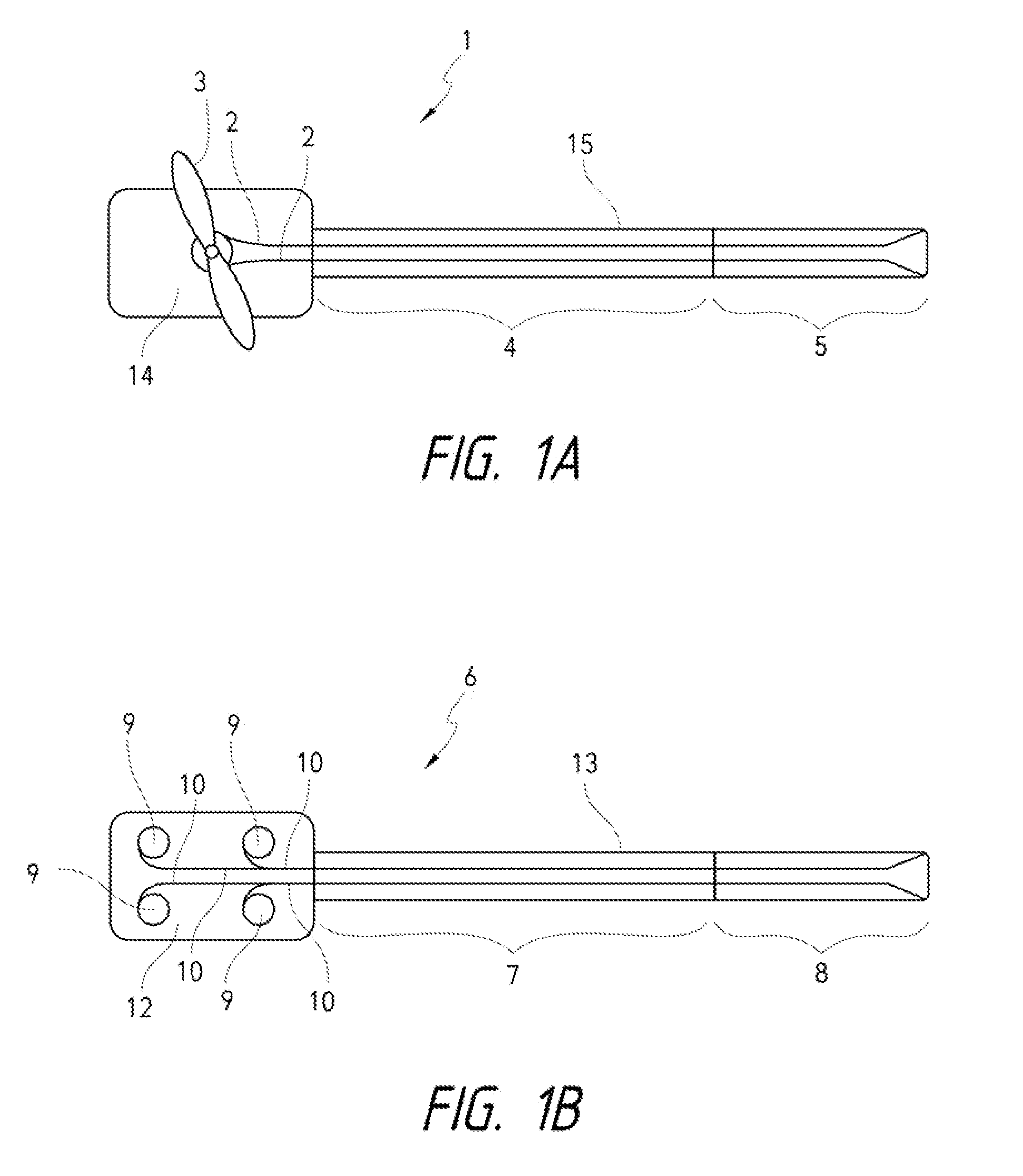
[0047]Referring to FIG. 1A, a conventional manually-steerable catheter (1) is depicted. Pullwires (2) may be selectively tensioned through manipulation of a handle (3) on the proximal portion of the catheter structure to make a more flexible distal portion (5) of the catheter bend or steer controllably. The pull wires can run from the proximal to distal end of the catheter terminating at a control r...


PUM

PropertyMeasurementUnit
diameteraaaaaaaaaa
lengthaaaaaaaaaa
lengthaaaaaaaaaa

Abstract

Systems and methods for integrating and / or registering a shape sensing fiber in or to various instruments are described herein. Registration fixtures and registration techniques for matching the coordinate system of a fiber to the coordinate system of an elongate instrument or other device are provided. Various systems and methods for integrating a shape sensing fiber into an elongate instrument or other device are also described herein.

Description

CROSS-REFERENCE TO RELATED APPLICATION[0001]This application claims the benefit of priority to U.S. Prov. Pat. App. 61 / 513,488 filed Jul. 29, 2011, which is incorporated herein by reference in its entirety for all purposes. This application relates to and incorporates herein by reference in its entirety for all purposes the patent application filed on the same day as the present application and titled “SYSTEMS AND METHODS UTILIZING SHAPE SENSING FIBERS”.FIELD OF THE INVENTION[0002]The present apparatus, systems and methods relate generally to apparatus and methods for integrating and / or registering a shape sensing fiber in or to an instrument or device.BACKGROUND[0003]Currently known minimally invasive procedures for diagnosis and treatment of medical conditions use elongate instruments, such as catheters or more rigid arms or shafts, to approach and address various tissue structures within the body. For various reasons, it is valuable to be able to determine the 3-dimensional spati...

Claims


Application Information

Patent Timeline
Patent Type & Authority Patents(United States)
IPC IPC(8): G02B6/00G02B6/06G02B6/38A61B5/06G01L1/24A61M25/01A61B1/005A61B19/00
CPCA61B5/065A61B1/0051A61B2019/5261A61M25/0147A61M2025/0166G01L1/242A61B2034/2061A61B1/009A61B2017/00292A61B2562/12A61B34/20G01B11/24
Inventor WONG, SERENA H.HSU, JASON J.MACNAMARA, FRANCISREIS, GENESCHLESINGER, RANDALL L.TANNER, NEAL A.
Owner AURIS HEALTH INC
Why Eureka
Try Eureka