Fasteners with shape changing bellows and methods using same

a technology of shape changing bellows and fasteners, which is applied in the field of fasteners with shape changing bellows and methods using same, can solve problems such as human or animal use, and achieve the effects of preventing slipping or accidental displacement of implants, preventing damage to adjacent joints, and accurate placemen

Active Publication Date: 2015-09-22
XTRAVERSE
View PDF28 Cites 84 Cited by
  • Summary
  • Abstract
  • Description
  • Claims
  • Application Information

AI Technical Summary

Benefits of technology

[0020]Some embodiments of the fastener provide angularity between the tubular members, and still other embodiments demonstrate that the tubular members do not need to be made of shape memory material entirely but may instead be of standard surgical materials and joined by bellows of shape memory material. The invention also includes fastening methods and medical procedures using the bellows fasteners described herein.
[0021]One or more aspects of the invention are as follows: to allow compression across an object's surfaces, to prevent slipping or accidental displacement of the implant, to intrinsically afford rotational and torsional stability, and to prevent destruction of adjacent joints. Several embodiments provide a cannulation for accurate placement, rapid placement, and the option of maintaining a pin across adjacent surgical sites if needed. Other aspects will be apparent from review and consideration of the drawings and description. Also, most of the tools required for the placement of the fastener are readily available in most operating rooms, negating the need for large amounts of specialized tooling.
[0022]The problems these embodiments resolve as pertains to osteosynthesis include: providing reliable compression across a fusion or osteosynthesis site, preventing unwanted distraction of an osteosynthesis site, provide rotational stability, preventing the destruction of adjacent joints, and allowing the option for a wire to remain in the surgical site and adjacent surgical sites at the same time as the invention if the surgeon so desires.

Problems solved by technology

These include but are not limited to alloys composed of iron, nickel, and manganese or iron, manganese, and silicon, some of which are not biocompatible and therefore not for use in human or animal subjects.

Method used


Image

  • Fasteners with shape changing bellows and methods using same
  • Fasteners with shape changing bellows and methods using same
  • Fasteners with shape changing bellows and methods using same

Examples


first embodiment

Operation of First Embodiment

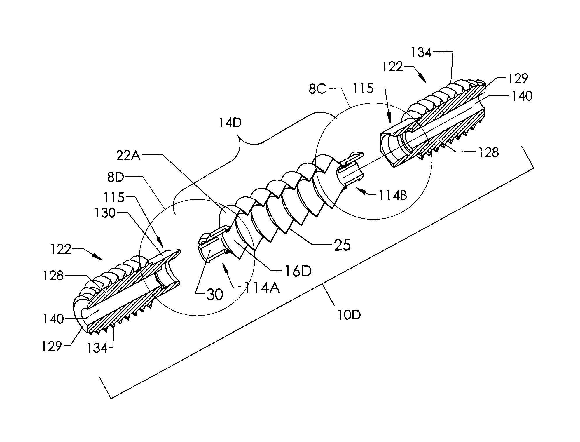
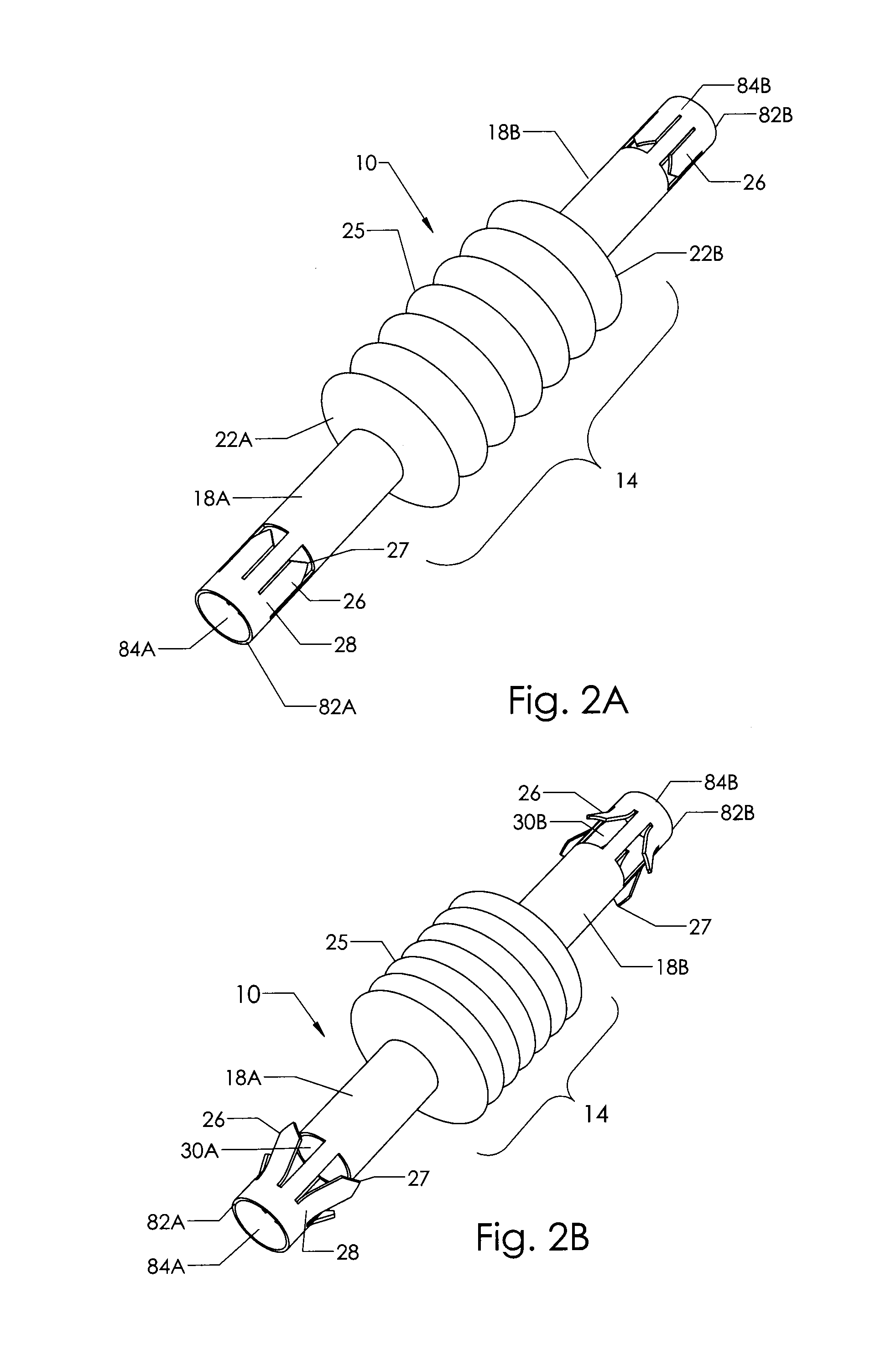
[0065]Fastener 10, as well as the other embodiments described herein, may be made from a shape memory alloy, such as Nitinol, though there are other shape changing materials available that also may be used. When any of these embodiments are used, say for a surgical procedure like a hammertoe correction, the properties of the metal or other material allow it to exist in different shapes at different temperatures. For example, when the Nitinol embodiment is moved from a cool or cold state, at which time it is in its martensite phase, and then implanted in the body and warmed to body temperature, it will undergo a change in its shape as it transforms to its austenite phase.

[0066]As shown again in FIGS. 2A and 2B, bellows 10 will shorten along its axial length, like an accordion, during its phase change from a martensitic phase to an austenitic phase. At the same time, barbs 26 on sleeves 18A and 18B will go through a phase change as well, expanding radially...

second embodiment

Operation of Second Embodiment

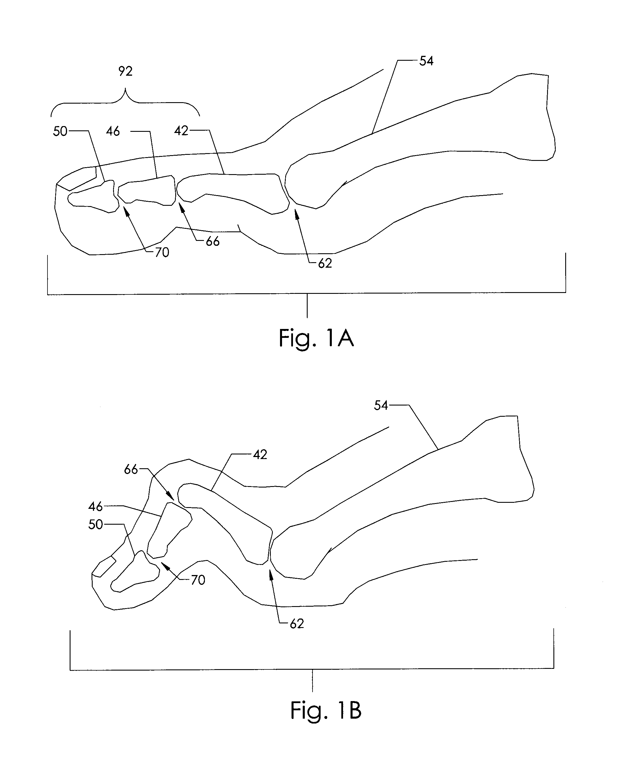
[0077]The application of the second embodiment requires the proximal phalanx and the middle phalanx to be prepared with angular cuts. The cut surface of the proximal or middle phalanx, instead of being cut perpendicular to the long axis of the bone, is cut at an angle to the long axis. The sum of the angles cut into both phalanxes is such that it matches the built-in angle of the embodiment; say ten to fifteen degrees for a toe or whatever the angle of the embodiment.

[0078]The step wise application of the embodiment is otherwise the same as FIGS. 5A through 5F. The proximal phalanx is cut and the middle phalanx is cut, each at one-half of the desired full angle. A guide wire is placed axially into the proximal phalanx and the phalanx is then counterbored to create a hole for the implant. The guide wire is then removed and driven axially into the middle phalanx and out the end of the toe. Again the guide wire is positioned so that it is nearly flush with...

third embodiment

Operation of Third Embodiment

[0082]The joint surfaces are prepared as before for the second embodiment. Proximal phalanx 42 and middle phalanx 46 are surgically prepared as before as shown in FIG. 6B. Here abutment surface 78 of proximal phalanx 42 and abutment surface 74 of middle phalanx 46 are prepared so they are at an angle to the long axis of each phalanx respectively. If the surgeon or user wants to fuse the two bones at ten degrees, for instance, then the cut surfaces must be prepared so that the angle formed between the long axes of proximal phalanx 42 and middle phalanx 46 equals ten degrees when both cut surfaces are placed end to end. For example, one surface could be cut at zero degrees or perpendicular to the long axis of the phalanx while the surface of the other phalanx is cut at ten degrees. Alternatively, both phalanges could be cut equally at five degrees. The surgeon will need to choose the implant that is designed to bend ten degrees.

[0083]If the surgeon wants t...


PUM


Abstract

A fastening device having a bellows made of a material that changes shape when activated by a catalyst, and having a pleated structure that contracts from an extended state to a contracted state upon activation. The shape changing material may be a shape memory metal alloy, shape memory polymer or elastic memory composite. A method of using this fastener provides apposition and compression of abutment surfaces to join together two pieces of material, and is suitable for joining apposing bone surfaces together to heal fractures via the use of orthopedic hardware.

Description

TECHNICAL FIELD[0001]The present invention relates generally to the joining and compressing together the surfaces of two or more pieces or parts by utilizing a bellows made from a shape memory material. Anchoring elements at opposite ends of the bellows are inserted into or attached to the respective pieces or parts to be joined together. These could be two or more pieces of wood, plastic, metal, bone, or combinations thereof, though not limited to any of these in particular. More specifically, the present invention has an application in the joining of two bone surfaces together for the purposes of osteosynthesis, or of bone fusion, and it relates particularly to a new and improved orthopedic endoprosthesis for fusing the bones together in a toe or finger.BACKGROUND OF THE INVENTION[0002]The medical term for a toe or finger is a phalange and any individual bone within a toe or finger is called a phalanx. Deformities of the phalanges are common conditions encountered by surgeons. The...

Claims


Application Information

Patent Timeline
Patent Type & Authority Patents(United States)
IPC IPC(8): A61B17/84A61B17/56A61B17/86
CPCA61B17/844A61B17/8685A61B17/866A61B17/864A61B2017/564A61B17/7225A61B2017/00867
Inventor BIESINGER, DAVID P.BIESINGER, JAMES A.
Owner XTRAVERSE
Why Eureka
Try Eureka