Arrangement for introducing a liquid medium into exhaust gases from a combustion engine

a technology of liquid medium and combustion engine, which is applied in the direction of machines/engines, mechanical equipment, transportation and packaging, etc., can solve the problems of lumps over time blocking the exhaust line, and it is difficult to avoid the contact of urea solution supplied with the internal wall surface of the exhaust line in an unvaporised state,

Active Publication Date: 2015-09-22
SCANIA CV AB
View PDF7 Cites 5 Cited by
  • Summary
  • Abstract
  • Description
  • Claims
  • Application Information

AI Technical Summary

Benefits of technology

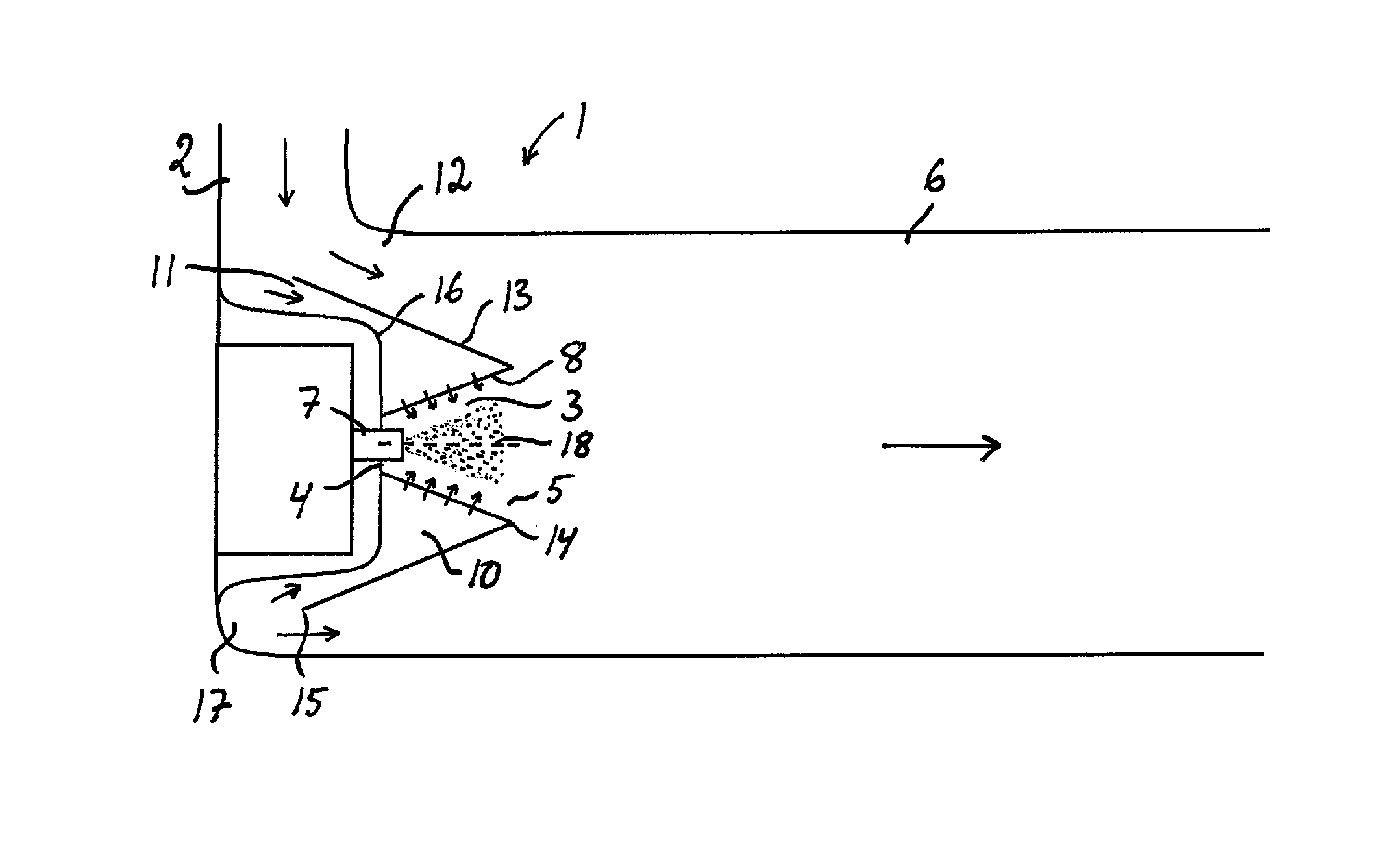
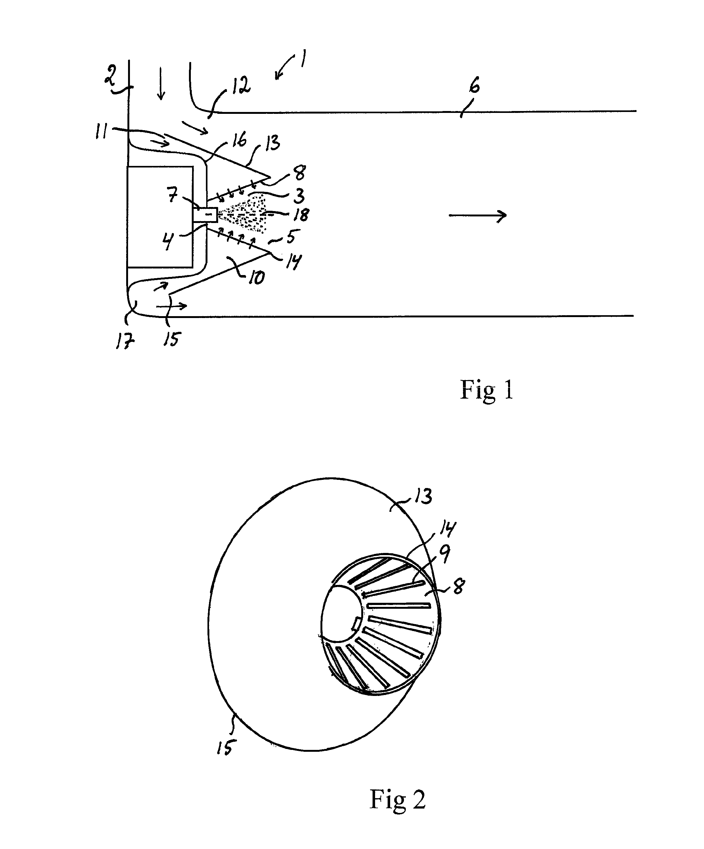
[0017]Diverting only a portion of the exhaust flow to the gathering chamber in order to pass through the throughflow apertures of the casing makes it possible for said apertures to be dimensioned to apply a constriction to that portion of the exhaust flow without appreciably affecting the pressure of the portion of the exhaust flow which is led directly into the mixing duct via the bypass duct without passing through the gathering chamber and the injection chamber. The pressure increase built up by the exhaust gases in the gathering chamber will therefore make only a limited contribution to the total backpressure of the exhaust gases in the exhaust line. Applying a pressure increase to the exhaust gases which accumulate in the gathering chamber makes it possible for the flow of exhaust gases into the injection chamber to be caused to become substantially evenly distributed among the various throughflow apertures. Uniform distribution of these apertures in the circumferential direction of the casing thus makes it possible to achieve an inflow of exhaust gases into the injection chamber in a manner substantially symmetrical about the centreline of the injection chamber. It thus becomes possible to drive the finely divided medium towards the centre of the injection chamber so that it is prevented from encountering the wall surfaces of the injection chamber and the wall surfaces of the mixing duct in the region nearest to the injection chamber. The result is that the small drops of the liquid medium are spread well out in the exhaust gases in the mixing duct before having an opportunity to encounter any wall surface thereof, thereby eliminating or at least substantially reducing the risk of lump formation such as described above.
[0019]Another advantage of diverting only a small portion of the total exhaust flow to the gathering chamber is that the exhaust flow into the gathering chamber will vary to only a limited extent when there are variations in the total exhaust flow. This means that the exhaust gases led into the injection chamber via the throughflow apertures of the casing will have a substantially similar effect on the injected liquid medium in different operating conditions and that the desired effect on the injected liquid medium is thus achievable in widely varying operating conditions.
[0020]According to another embodiment of the invention, the bypass duct surrounds the gathering chamber and is demarcated from it by a cowl situated between the gathering chamber and the bypass duct. This makes possible a compact and space-saving configuration of the arrangement.

Problems solved by technology

It is difficult, however, to avoid part of the urea solution supplied coming into contact with and becoming attached to the internal wall surface of the exhaust line in an unvaporised state.
The relatively cool urea solution may cause local lowering of the temperature in that region of the exhaust line, which may lead to the formation in that region of a film of urea solution which is then entrained by the exhaust flow.
Such urea lumps may over time block an exhaust line.

Method used


Image

  • Arrangement for introducing a liquid medium into exhaust gases from a combustion engine
  • Arrangement for introducing a liquid medium into exhaust gases from a combustion engine

Examples


Embodiment Construction

[0025]FIG. 1 illustrates an arrangement 1 according to the present invention for introducing a liquid medium into exhaust gases from a combustion engine. The arrangement may for example be situated in an exhaust line upstream of an SCR catalyst in order to introduce a liquid reducing agent in the form of urea or ammonia into the exhaust line upstream of the SCR catalyst, or be situated in an exhaust post-treatment device in order to introduce a liquid reducing agent in the form of urea or ammonia upstream of an SCR catalyst which forms part of the exhaust post-treatment device.

[0026]The arrangement 1 comprises a line 2 intended to receive exhaust gases from a combustion engine and to lead them towards an exhaust post-treatment unit, e.g. in the form of an SCR catalyst. The arrangement 1 further comprises an injection chamber 3 with a closed rear end 4 and an open forward end 5. The injection chamber 3 is connected via its open forward end 5 to a mixing duct 6 which forms part of the...


PUM

PropertyMeasurementUnit
circumferenceaaaaaaaaaa
pressureaaaaaaaaaa
temperatureaaaaaaaaaa

Abstract

Arrangement for introducing a liquid medium into exhaust gases from a combustion engine: an injector for injecting the liquid medium into an injection chamber (3), a casing (8) which surrounds the injection chamber, a mixing duct (6), a gathering chamber (10) which surrounds the casing and is connected to the injection chamber via throughflow apertures of the casing, and a bypass duct (12) for leading exhaust gases into the mixing duct without passing through the gathering chamber and the injection chamber. The inlet (11) of the gathering chamber diverts a portion of the exhaust gases to flow into the gathering chamber, and then into the injection chamber via the throughflow apertures, and thereafter into the mixing duct, while the bypass duct leads another portion of the exhaust gases into the mixing duct in order to be mixed there with the diverted exhaust gases.

Description

CROSS-REFERENCE TO RELATED APPLICATIONS[0001]The present application is a 35 U.S.C. §§371 national phase conversion of PCT / SE2011 / 051106, filed Sep. 14, 2011, which claims priority of Swedish Application No. 1051014-7, filed Sep. 30, 2010, the contents of which are incorporated by reference herein. The PCT International Application was published in the English language.FIELD OF THE INVENTION, AND BACKGROUND OF THE INVENTION[0002]The present invention relates to an arrangement for introducing a liquid medium, e.g. urea, into exhaust gases from a combustion engine[0003]To meet prevailing exhaust cleaning requirements, today's motor vehicles are usually provided with a catalyst in the exhaust line to effect catalytic conversion of environmentally hazardous constituents of the exhaust gases to environmentally less hazardous substances. A method which has been employed for achieving effective catalytic conversion is based on injecting a reducing agent into the exhaust gases upstream of t...

Claims


Application Information

Patent Timeline
Patent Type & Authority Patents(United States)
IPC IPC(8): F01N3/02B01F5/04B01F3/04F01N3/28F01N3/10F01N3/20
CPCF01N3/10B01F3/04049B01F5/045F01N3/2066F01N3/2892F01N2240/02F01N2240/20F01N2610/02F01N2610/08F01N2610/1453Y02T10/24Y02T10/12B01F23/2132B01F2025/931B01F25/313F01N3/20F01N3/24F01N3/28F01N13/08F01N3/206
Inventor LOMAN, PETER
Owner SCANIA CV AB
Why Eureka
Try Eureka