
Vibratory feed mechanism for pellet fuel combustion device

a technology of vibration feed and combustion device, which is applied in the combustion process, lighting and heating apparatus, stoves or ranges, etc., can solve the problems of noisy mechanical parts, known pellet fuel combustion device, stove and pellet fuel barbeques

Active Publication Date: 2015-09-22
FREEMAN MARK D
View PDF9 Cites 16 Cited by
  • Summary
  • Abstract
  • Description
  • Claims
  • Application Information

AI Technical Summary

Benefits of technology

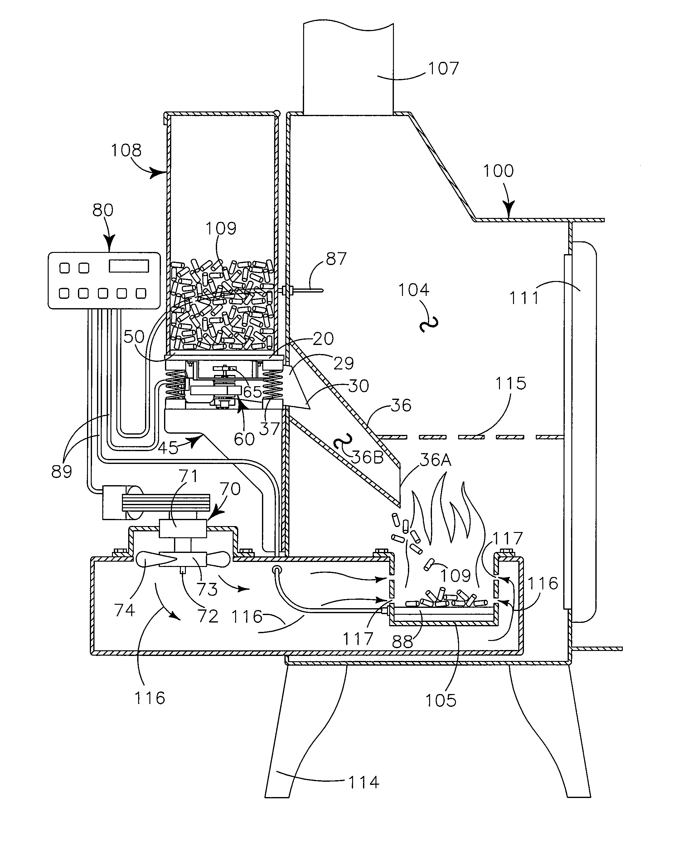
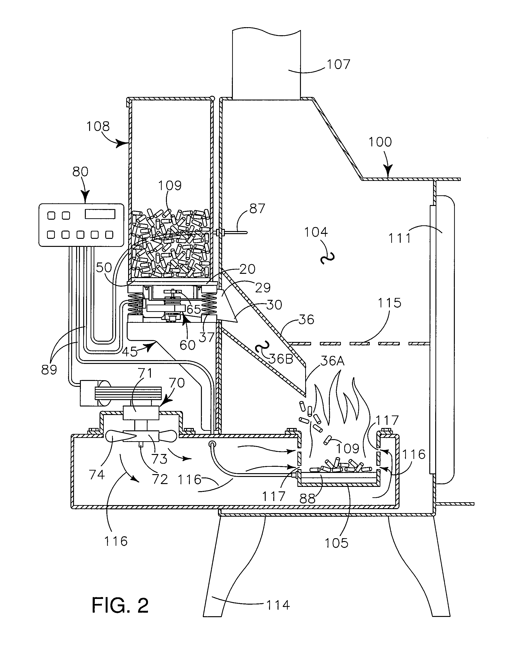
The vibratory feed mechanism in this patent allows for precise measurement and control of pelletized fuel feed to a fire pot. It is controlled by a user-set parameter that determines the rate of fuel feed and temperature settings. Additionally, the mechanism allows for precise control of heat levels and fuel consumption.

Problems solved by technology

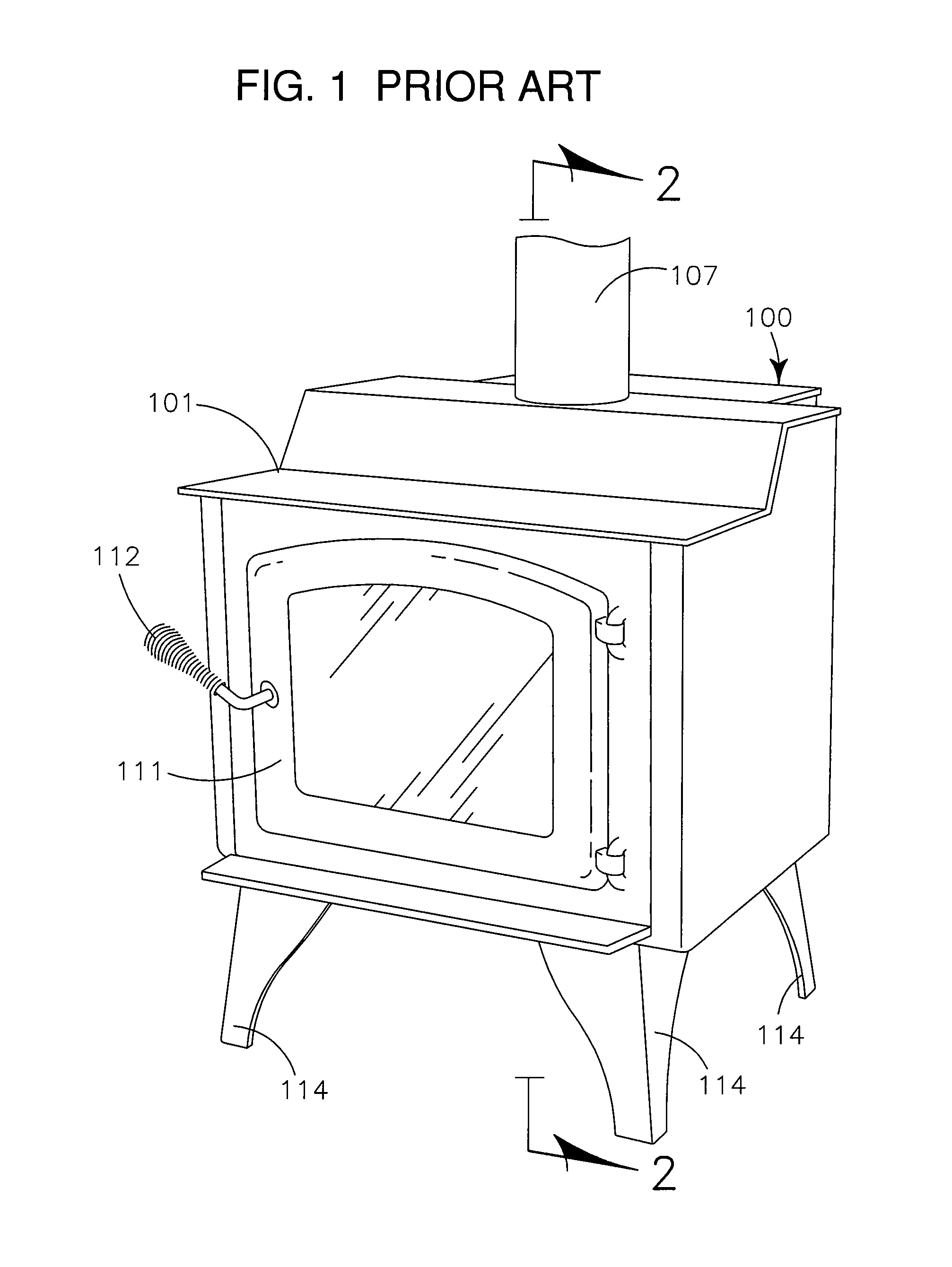
Unfortunately, known pellet fuel combustion devices, including but not limited to pellet fuel stoves and pellet fuel barbeques suffer from a universal problem that is inherent in known pellet fuel feed mechanisms by which the pelletized fuel is moved from a fuel reservoir, to a fire pot where the fuel is combusted to generate heat.
The starting and stopping of the auger motor, the reduction gear assembly and the auger causes wear to the various mechanical components and frequently leads to the mechanical parts being noisy.
Further, because the fuel pellets have “rough” surfaces that enhance the tendency to “catch” fire, the fuel pellets also have the tendency to “wear on” and “abrade” the surfaces of the auger tube and the auger, which after periods of use may cause “gaps” and “spaces” between edge portions of the auger and the auger tube where fuel pellets may become “caught” and “trapped” causing binding such that the auger may not spin freely within the auger tube.
Such binding exacerbates the wear on the auger, the auger tube, the reduction gears and the auger motor.
It is well known in the pellet stove industry that the primary cause of breakdown and dysfunction of pellet fuel combustion devices is malfunction and wearing out of the auger, the auger motor and the auger reduction gear assembly which may collectively be referred to as the “feed mechanism.” Further, one of the primary complaints of pellet fuel combustion devices is the noise generated by the starting and stopping of the feed mechanism.
Because pellet fuel combustion devices require regular periodic feeding of fuel pellets to operate, when the auger, the auger motor, or the reduction gear assembly malfunction, the pellet fuel combustion device is inoperable, will not generate heat, which may in some instances, lead to significant damage to the user's premises, such as frozen pipes, and the like.

Method used


Image

  • Vibratory feed mechanism for pellet fuel combustion device
  • Vibratory feed mechanism for pellet fuel combustion device
  • Vibratory feed mechanism for pellet fuel combustion device

Examples


Embodiment Construction

[0053]The readers of this document should understand that the embodiments described herein may rely on terminology used in any section of this document and other terms readily apparent from the drawings and the language common therefore as may be known in a particular art and known or indicated or provided by dictionaries. Dictionaries were used in the preparation of this document. Widely known and used in the preparation hereof are Webster's Third New International Dictionary (©1993), The Oxford English Dictionary (Second Edition, ©1989), The New Century Dictionary (©2001-2005) and the American Heritage Dictionary of the English Language (4th Edition©2000) all of which are hereby incorporated by this reference for interpretation of terms used herein to more adequately or aptly describe various features, aspects and concepts shown or otherwise described herein.

[0054]This document is premised upon using one or more terms or features shown in one embodiment that may also apply to or b...


PUM


Abstract

A vibratory feed mechanism for pellet fuel combustion device provides a spring-mounted feed plate communicating with a fuel reservoir and vibrated by an electric motor carrying an offset counterweight to move pelletized fuel from a first position on the feed plate to a feed orifice defined in the feed plate for communication of the pelletized fuel to a metering channel and a drop tube for conveyance to a fire pot. A control board communicating with an igniter, at least one thermocouple, a combustion fan, and the electric motor allow a user to set a desired parameter which controls the rate of pelletized fuel feed and temperature and operating conditions.

Description

RELATED APPLICATIONS[0001]There are no patent applications related hereto previously filed in the United States or in any foreign country.BACKGROUND OF INVENTION[0002]1. Field of Invention[0003]This invention relates to combustion devices, and more particularly to a pellet fuel feed mechanism, and even more particularly to a vibratory feed mechanism for moving pelletized fuel from a fuel reservoir to a fire pot in a combustion device for generating heat.[0004]2. Background and Description of Prior Art[0005]For centuries wood has been burned in pits, fireplaces, stoves, and barbeques to provide heat. Over time, the methods and apparatus in which wood was burned to provide heat improved. For instance, pits led to hearths. Hearths led to stoves. Stoves led to furnaces and registers. Many of these improvements followed or resulted from advances in science, advancements in manufacturing, and also the availability of resources.[0006]Similar to changes and advancements in the apparatus use...

Claims


Application Information

Patent Timeline
Patent Type & Authority Patents(United States)
IPC IPC(8): A47J37/00F23B50/12F23K3/16A47J37/07
CPCF23K3/16F23B50/12A47J37/0704F24B1/024F24B13/04F23G2205/125
Inventor FREEMAN, MARK D.
Owner FREEMAN MARK D
Learn More