Eureka AIR delivers breakthrough ideas for toughest innovation challenges, trusted by R&D personnel around the world.

Method of aligning an axisymmetric vibrating sensor inertial navigation system and corresponding inertial navigation system

a technology of vibrating sensor and inertial navigation system, which is applied in the direction of acceleration measurement using interia force, turn-sensitive devices, instruments, etc., can solve the problems of drift error that is a function of position, presentation drift error, compensation is never perfect, etc., and achieve the effect of minimizing the effect of drift error on navigation performan

Active Publication Date: 2015-09-29
SAFRAN ELECTRONICS & DEFENSE
View PDF4 Cites 0 Cited by
  • Summary
  • Abstract
  • Description
  • Claims
  • Application Information

AI Technical Summary

Benefits of technology

[0016]An object of the invention is to minimize the effects of drift error on the navigation performance of the inertial unit.
[0019]to minimize alignment errors resulting from the drift error of the sensor; and
[0020]to improve the repeatability of drift error from one alignment to another, thus making it possible to observe it and therefore to compensate it, since the position of the vibration remains the same.

Problems solved by technology

Axially symmetrical vibrating gyroscopes used in free-gyro mode present the feature of presenting drift error that is a function of the position of the vibration relative to the base of the sensor.
This drift error is naturally modeled and compensated, but such compensation is never perfect.
There thus remains drift error that is a function of position.
When such gyroscopes are used in navigation units, this drift error constitutes one of the sources of error in the unit.
In addition, the drift error also varies as a function of temperature and as a function of time.
When a navigation unit is started, the initial position of the vibration is a priori arbitrary, and it can vary from one start-up to another; the drift error associated with the position of the vibration is thus variable and can disturb the quality of the alignment.

Method used


Image

  • Method of aligning an axisymmetric vibrating sensor inertial navigation system and corresponding inertial navigation system
  • Method of aligning an axisymmetric vibrating sensor inertial navigation system and corresponding inertial navigation system

Examples


Embodiment Construction

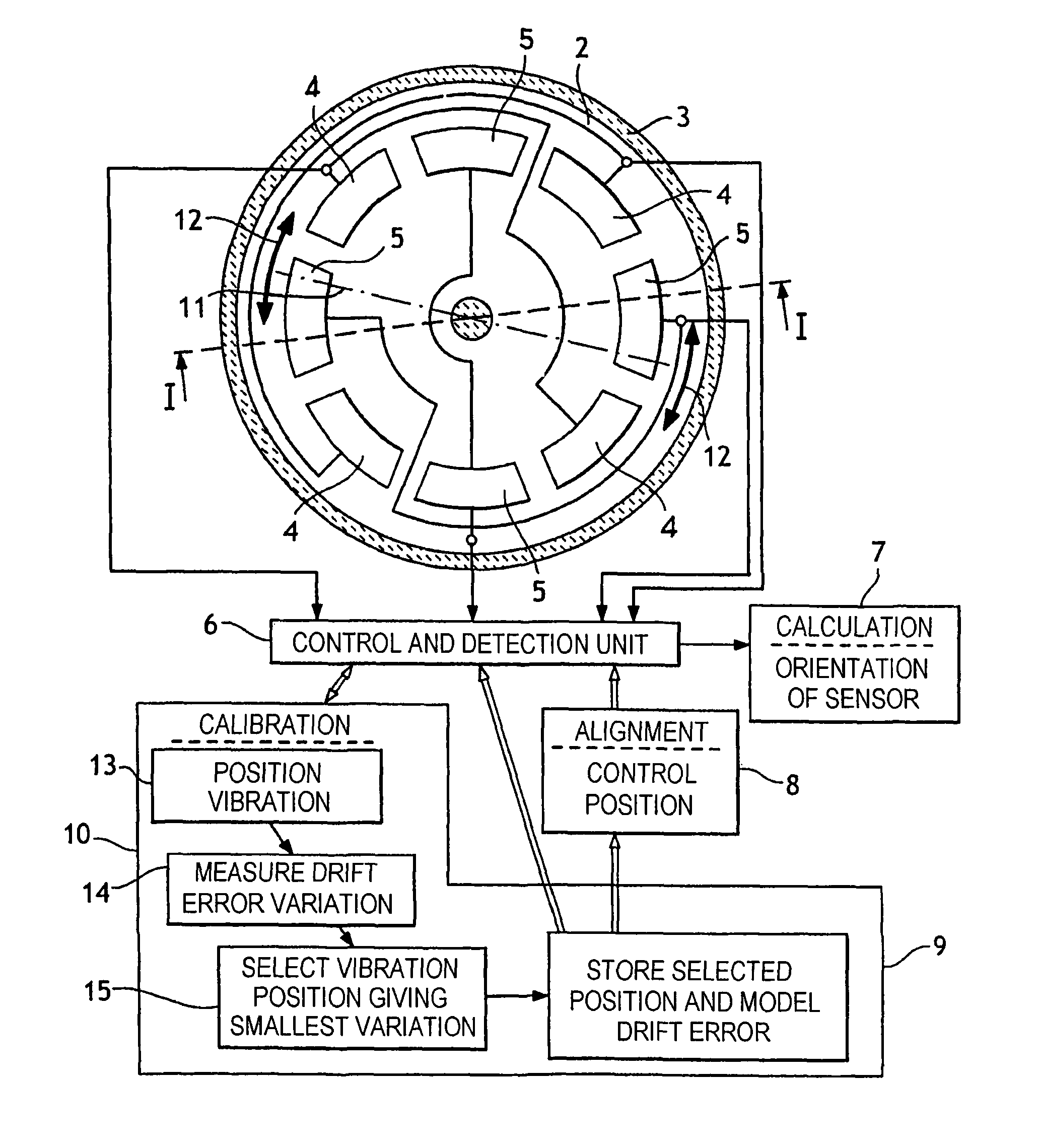
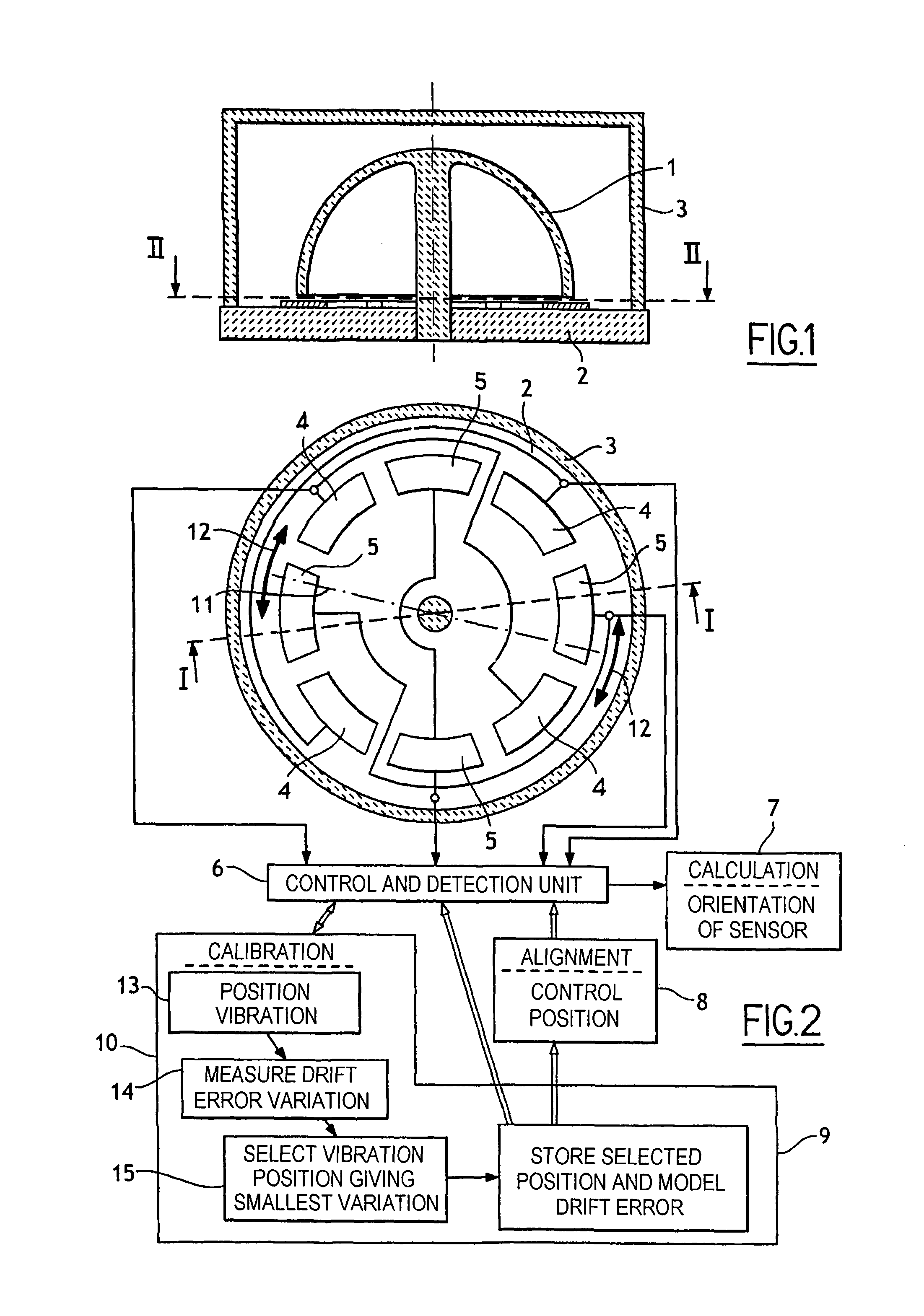
[0028]With reference to the figures, the hemispherical-bell vibrating sensor shown comprises in known manner a silica bell 1 mounted on a base 2 likewise made of silica, the bell 1 being surrounded by a sealed housing 3 enabling the sensor to be evacuated.

[0029]Also in known manner, the inside surface of the bell 1 is metal-plated, as is its bottom edge that extends facing two pairs of control electrodes 4 and two pairs of detection electrodes 5 suitably connected to a control and detection unit 6 for generating vibration 11 represented by a chain-dotted line in FIG. 2, and of position that can be controlled by the control unit 6.

[0030]Also in known manner, the control and detection unit 6 is connected to a member 7 for calculating the orientation of the sensor on the basis of detection signals received from the control and detection unit.

[0031]According to the invention, the alignment stage is performed by exciting the sensor with a control signal that positions the resulting vibra...


PUM


Abstract

The method of aligning an inertial unit having an axially symmetrical vibrating sensor that generates vibration comprises the step of establishing the vibration in a position for which the sensor presents variation in drift error that is the smallest relative to variation in drift error for other positions of the vibration.

Description

BACKGROUND OF THE INVENTIONField of the Invention[0001]The present invention relates to a method of aligning an inertial unit having an axially symmetrical vibrating sensor, and to a corresponding inertial unit including an axially symmetrical vibrating sensor.BRIEF DESCRIPTION OF THE RELATED ART[0002]In order to determine the orientation of a carrier, in particular in order to navigate an airplane, it is common practice to use an inertial unit that includes axially symmetrical vibrating sensors such as hemispherical-bell vibrating sensors or Quapasons.[0003]It is also known that an axially symmetrical vibrating sensor is adapted to operate either in free-gyro mode or in rate-gyro mode. In free-gyro mode, the vibration is sustained but position is left free; when the orientation of the carrier varies, the position of the vibration relative to the base is representative of the angle through which the carrier has turned.[0004]In rate-gyro mode, vibration is sustained and its position ...

Claims


Application Information

Patent Timeline
Patent Type & Authority Patents(United States)
IPC IPC(8): G01C19/5691G01C19/56
CPCG01C19/5691
Inventor CARON, JEAN-MICHEL
Owner SAFRAN ELECTRONICS & DEFENSE
Why Eureka
Eureka Blog
Learn More