
Method and apparatus for mapped I/O routing in an interconnect switch

a technology of interconnection switch and mapped i/o, which is applied in the direction of instruments, electric digital data processing, etc., can solve the problems of inability to manufacture new revisions of silicon, inability to correct errors, and inability to meet the requirements of new silicon revisions,

Active Publication Date: 2015-09-29
MICROSEMI STORAGE SOLUTIONS US INC
View PDF18 Cites 27 Cited by
  • Summary
  • Abstract
  • Description
  • Claims
  • Application Information

AI Technical Summary

Benefits of technology

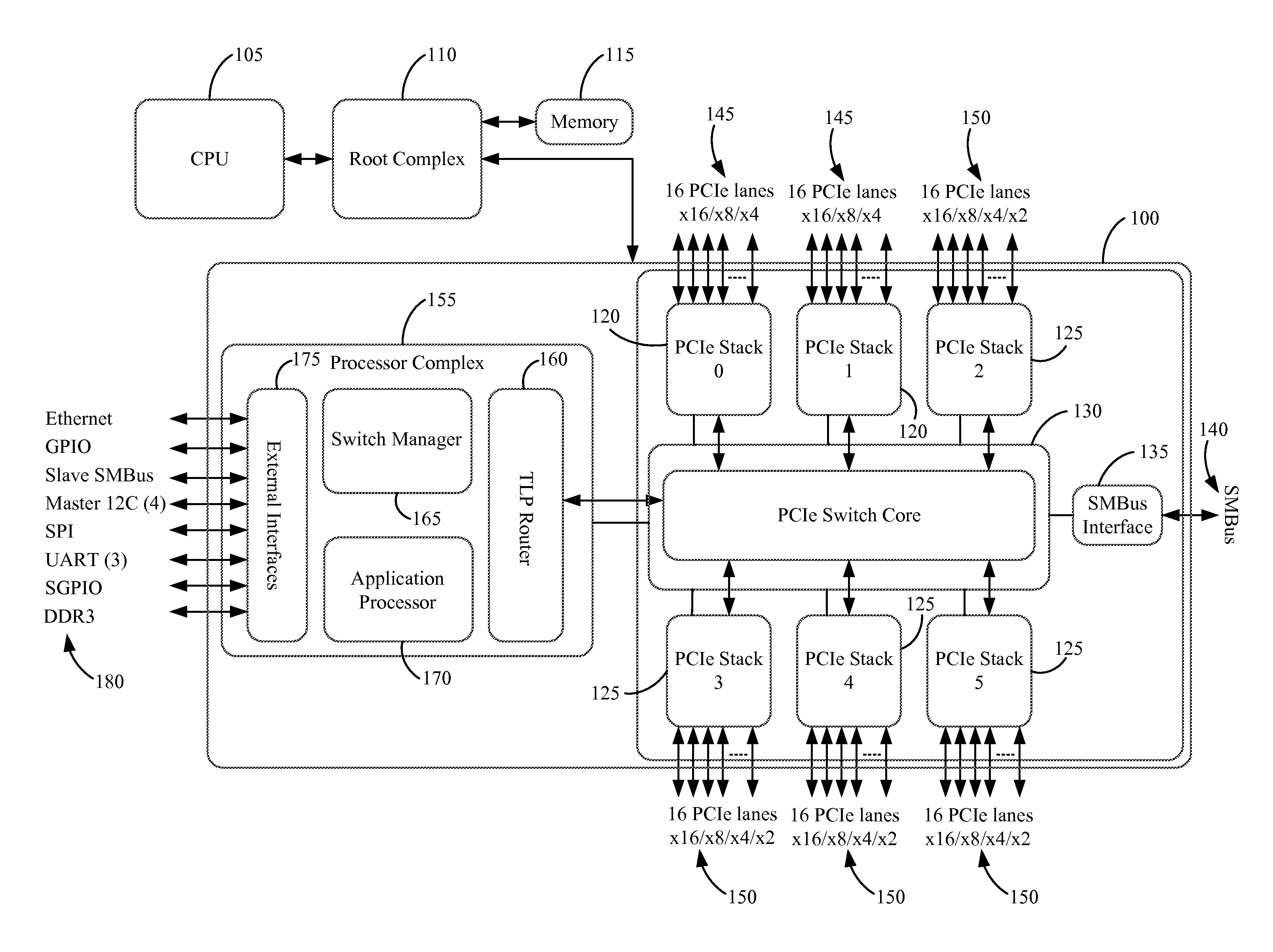
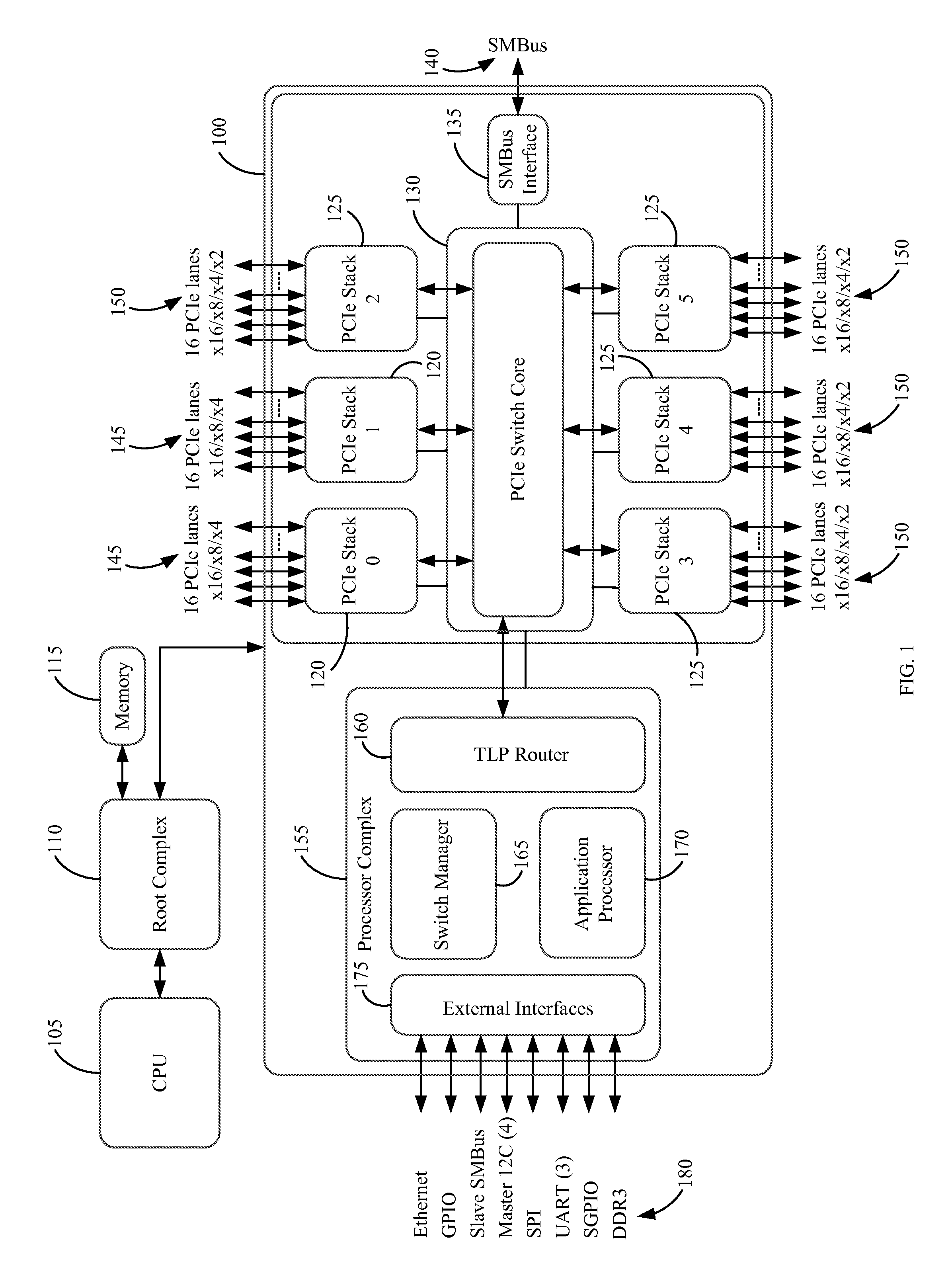
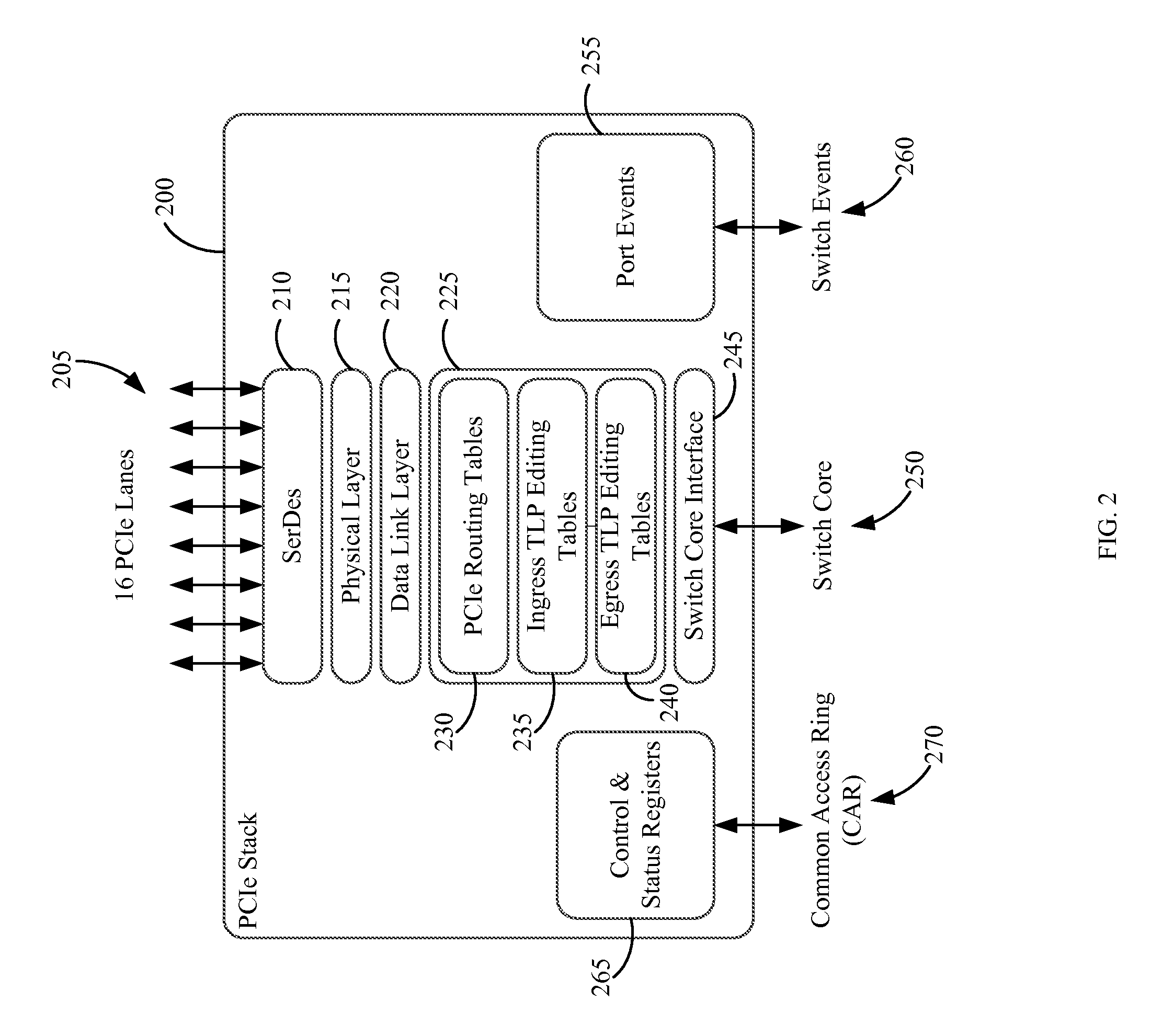
The present invention provides a flexible routing engine in a switch for coupling a CPU to a plurality of I / O devices through a root complex. The system and method allow for efficient routing and flexible configuration of the switch to meet different needs. The switch may be a PCIe switch operating in a PCIe switch fabric topology or a RapidIO switch operating in a RapidIO switch fabric topology. The switch stacks may receive a configuration request transaction layer packet from the root complex and the switch manager should interpret the packet and update at least one table of the switch stacks based on the interpretation. The system and method allow for non-standard routing of the transaction layer packet request utilizing mapped I / O routing in the switch. Overall, the invention allows for efficient and flexible connectivity between multiple root complexes and the various ports of the switch.

Problems solved by technology

If errors are made in the hard-coding of the routing functions during the fabrication process, new revisions of silicon are required to correct the errors.
Fabricating new revisions of silicon is an expensive and time-consuming process which undesirably delays the device time-to-market.

Method used


Image

  • Method and apparatus for mapped I/O routing in an interconnect switch
  • Method and apparatus for mapped I/O routing in an interconnect switch
  • Method and apparatus for mapped I/O routing in an interconnect switch

Examples


Embodiment Construction

[0030]Reference will now be made in detail to the preferred embodiments of the invention, examples of which are illustrated in the accompanying drawings. While the invention will be described in conjunction with the preferred embodiments, it will be understood that they are not intended to limit the invention to these embodiments. On the contrary, the invention is intended to cover alternatives, modifications and equivalents, which may be included within the spirit and scope of the invention as defined by the appended claims. Furthermore, in the following detailed description of the present invention, numerous specific details are set forth in order to provide a thorough understanding of the present invention. However, it will be obvious to one of ordinary skill in the art that the present invention may be practiced without these specific details. In other instances, well-known methods, procedures, components, and circuits have not been described in detail so as not to unnecessarily...


PUM


Abstract

A system and method are disclosed for a flexible routing engine in a PCIe switch. The system may include a switch manager that is enabled, through firmware, to configure one or more routing tables associated with a switch stack of a PCIe switch. To enable non-transparent bridging and non-standard routing, such as mapped I / O routing, the method may include receiving a transaction layer packet at a mapped I / O routed port of a PCIe switch, and performing translation of the requester ID of the packet utilizing tables that are updated by the firmware of the switch manager to route the packet through the switch.

Description

BACKGROUND OF THE INVENTION[0001]Peripheral Component Interconnect Express (PCIe) is a third generation Input Output (3GIO) system that implements a serial, switched-packet, point-to-point communication standard at the system level. PCI Express has achieved many advantages over the prior shared bus system, such as quality of service (QoS), high speed peer-to-peer communication between external devices, adaptability, and low pin counts. The basic PCI Express architecture includes a root complex, optionally, a PCI Express switch, and PCI Express endpoints.[0002]In the prior art implementation of a PCI Express switch for routing incoming data packets between root complex and endpoint devices, the transaction layer packet (TLP) routing functions of the switch are hard-coded into the switch. Hard-coding of the switch routing functions is performed during the initial silicon fabrication. If errors are made in the hard-coding of the routing functions during the fabrication process, new rev...

Claims


Application Information

Patent Timeline
IPC IPC(8): G06F13/00G06F13/40
CPCG06F13/4022
Inventor BROWN, DAVID ALANONUFRYK, PETER Z.
Owner MICROSEMI STORAGE SOLUTIONS US INC
Learn More