Reducing halo artifacts in electrophotographic printing systems

Active Publication Date: 2015-09-29
EASTMAN KODAK CO
View PDF9 Cites 36 Cited by
  • Summary
  • Abstract
  • Description
  • Claims
  • Application Information

AI Technical Summary

Benefits of technology

[0020]This invention has the advantage that the visibility of halo artifacts caused by fringe field effects in electrophotographic printing can be substantially reduced.
[0021]It has the additional advantage that the computations necessary to determine the corrected image can be performed efficiently so that the process can be

Problems solved by technology

Electrophotographic printing systems are susceptible to various printing artifacts where the

Method used


Image

  • Reducing halo artifacts in electrophotographic printing systems
  • Reducing halo artifacts in electrophotographic printing systems
  • Reducing halo artifacts in electrophotographic printing systems

Examples


Embodiment Construction

[0037]The invention is inclusive of combinations of the embodiments described herein. References to “a particular embodiment” and the like refer to features that are present in at least one embodiment of the invention. Separate references to “an embodiment” or “particular embodiments” or the like do not necessarily refer to the same embodiment or embodiments; however, such embodiments are not mutually exclusive, unless so indicated or as are readily apparent to one of skill in the art. The use of singular or plural in referring to the “method” or “methods” and the like is not limiting. It should be noted that, unless otherwise explicitly noted or required by context, the word “or” is used in this disclosure in a non-exclusive sense.

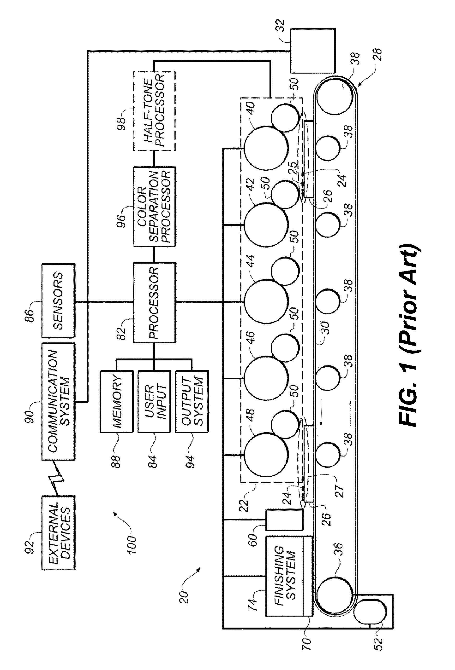
[0038]FIG. 1 is a system level illustration of one embodiment of an exemplary toner printer 20 which uses an electrophotographic process to produce printed images. In the embodiment of FIG. 1, toner printer 20 has a print engine 22 that deposits toner 24 ...


PUM


Abstract

A method for processing an input image to reduce halo artifacts in an electrophotographic printing system. The input image is automatically analyzed to determine an edge map image indicating light-side edge regions that include edge pixels that are adjacent to edge transitions in the input image and are on a lighter side of the edge transition. At least one edge region dilation operation to the edge map image to expand the light-side edge regions in a direction away from the edge transitions. A corrected image is formed by modifying the input pixels of the input image corresponding to the expanded light-side edge regions to determine corrected pixels having corrected pixel values. The corrected image is then printed using the electrophotographic printing system.

Description

FIELD OF THE INVENTION[0001]This invention pertains to the field of artifact reduction for electrophotographic printing, and more particularly to a method for reducing halo artifacts.BACKGROUND OF THE INVENTION[0002]Electrophotography is a useful process for printing images on a receiver (or “imaging substrate”), such as a piece or sheet of paper or another planar medium (e.g., glass, fabric, metal, or other objects) as will be described below. In this process, an electrostatic latent image is formed on a photoreceptor by uniformly charging the photoreceptor and then discharging selected areas of the uniform charge to yield an electrostatic charge pattern corresponding to the desired image (i.e., a “latent image”).[0003]After the latent image is formed, charged toner particles are brought into the vicinity of the photoreceptor and are attracted to the latent image to develop the latent image into a toner image. Note that the toner image may not be visible to the naked eye depending ...

Claims


Application Information

Patent Timeline
IPC IPC(8): G06T5/20G06K15/02G03G15/00G06T7/40G06T5/00G06T5/30G03G13/00G06K15/14H04N1/29H04N1/409G06T7/00
CPCG06T5/003G06T5/30G06T7/0085G06T7/408G03G15/55G06K15/1871H04N1/295G06K15/14H04N1/4092G06T2207/20024G06T2207/20192G03G15/50G03G2215/0429G06T5/002G06K15/128G06K15/1868G06T7/13G06T7/136H04N1/00
Inventor KUO, CHUNG-HUINEAMTU, HORIA
Owner EASTMAN KODAK CO
Why Eureka
Try Eureka