Flex-i-board

a technology applied in the field of counter-top cutting and chopping boards, can solve the problems of insignificant countertop vibration, difficult positioning of boards and stability, and significant amount of vibration (and consequent noise) transmitted, and achieve the effect of positioning boards and stability

Active Publication Date: 2015-10-06
FREY NICHOLAS GREGORY
View PDF14 Cites 0 Cited by
  • Summary
  • Abstract
  • Description
  • Claims
  • Application Information

AI Technical Summary

Benefits of technology

[0016]Because a significant amount, of the impact, of the cleaver or mallet is absorbed in compressing the legs, an insignificant amount of the impact force of the cleaver or mallet, on the board, reaches the countertop. This results in insignificant countertop vibration and consequently an insignificant amount of noise, when compared to the traditional cutting-chopping board.In addition, there is less wear to the cleaver blade edge because upon impact, the cutting-chopping board moves down under the impact force, and the blade edge comes to a more gradual stop as opposed to traditional stationary board where the cleaver blade hits the stationary cutting-chopping board surface more abruptly.

Problems solved by technology

However, what has always been a problem when chopping on a plastic or wooden (or rubber) board on a countertop with a cleaver or a meat softening mallet, is the significant amount of vibrations (and consequent noise) transmitted from the impact of the chopping cleaver or meat mallet on the cutting-chopping board, to the countertop and to items located on the countertop, near the board, Even the expensive 2-3 inch wooden boards, when hit with a chopping or pounding tool shake-up the countertop and are very noisy.
However, positioning the board and stability while chopping, can be challenging.
This results in insignificant countertop vibration and consequently an insignificant amount of noise, when compared to the traditional cutting-chopping board.

Method used


Image

  • Flex-i-board
  • Flex-i-board
  • Flex-i-board

Examples


embodiment 1

[0045]Additional embodiment 1, is shown in FIGS. 7A and 7B. About 300 mm (12 inch) of an approximately 300 mm by 600 mm (12 inch by 24 inch) or larger, piece of polypropylene or other appropriate plastic, is cut into five 125 mm (1.2 inch) strips. Each, of the strips, is alternately, heat bent into a wavy pattern as illustrated in FIG. 7A. The alternating wavy stripes section is heat bent approximately 180 degrees. This section serves as the compressible “legs”10 for the top section, which serves as the cutting-chopping board surface 14.

embodiment 2

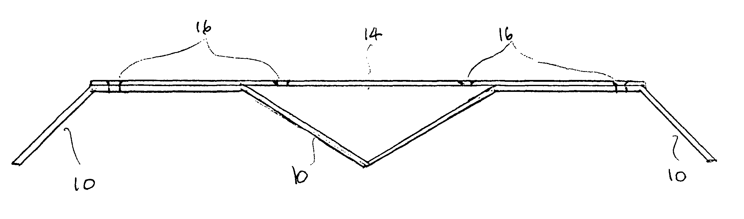
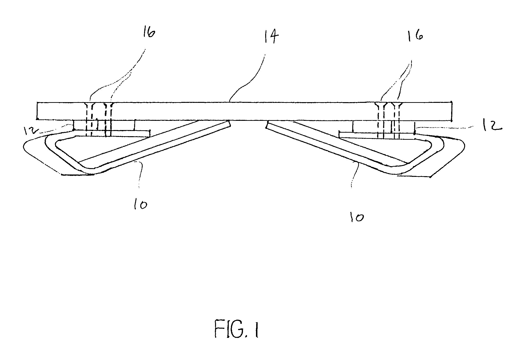
[0046]Additional embodiment 2, is shown in FIGS. 8A and 8B. A 300 mm (12 inch) by 600 mm (24 inch) or proportionally larger piece of polypropylene or other appropriate plastic is heat bent approximately 190 degrees at both ends with both extension arms (legs 10) pressing against the lower surface of the cutting-chopping board surface as illustrated. Cleaver impact on the surface of the board 14 would be countered by the resistance of compressing each of the circular ends and the upward forces exerted by each of the extension arms (legs 10) on the lower surface of the cutting board.

embodiment 3

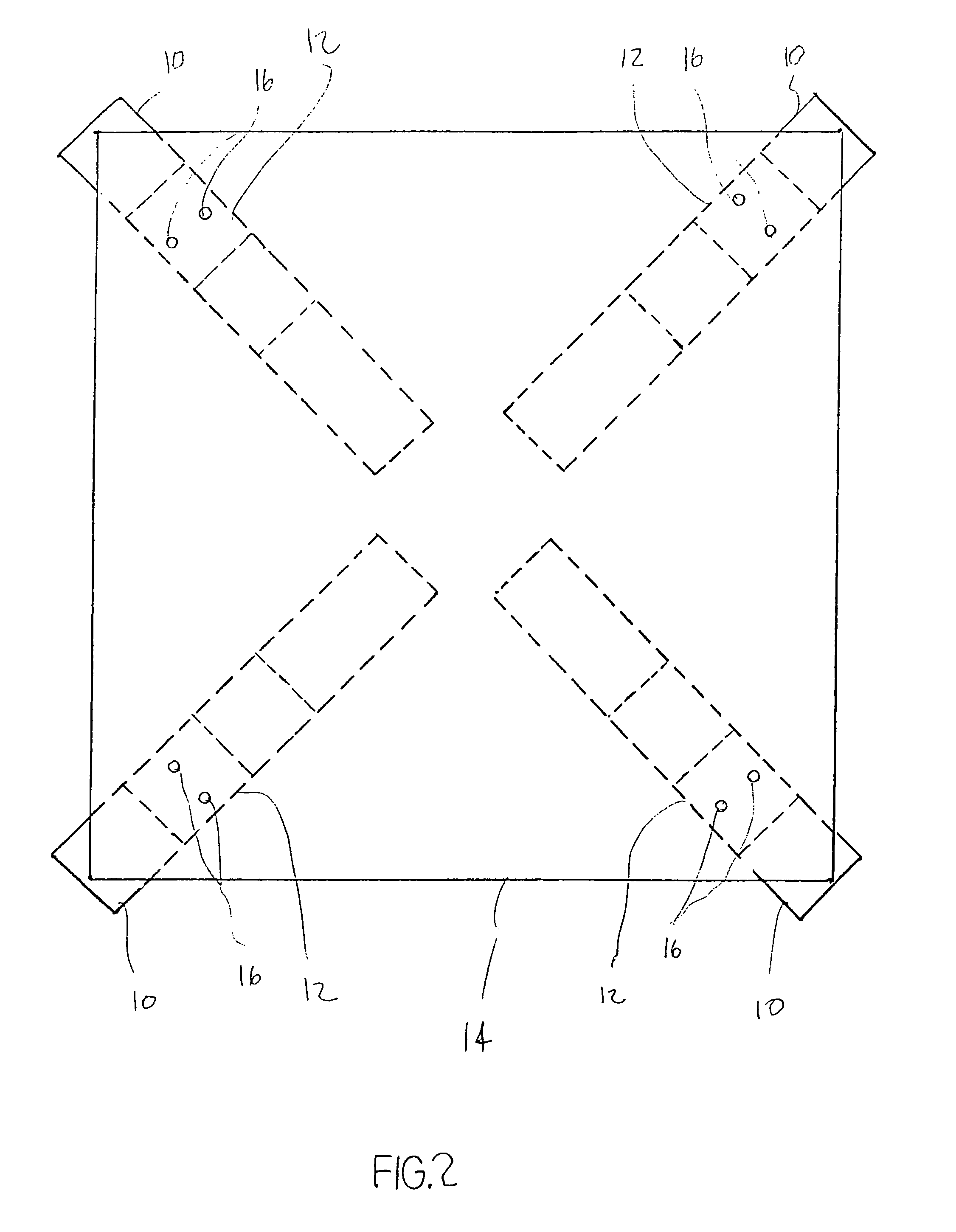
[0047]Additional embodiment 3, illustrated in FIGS. 9A and 9B, would be to initially position two approximately 300 mm (12 inch) by 300 mm (12 inch) or larger, plastic squares over each other then rotate one of them 90 degrees. The two pieces would be secured together with two #4-32×⅜'s countersunk stainless steel machine screws located near each of the four corners, hole 16 location as illustrated in FIG. 9B. Each, of the four corners, of the lower piece, are bent approximately 45 degrees. The 45 degree angle, of the four legs 10, allows for their flexing. The triangular shape of the legs 10 provide for a gradual increase in resistance, as the legs 10 flex, in response to cleaver or mallet impact on the surface of the upper piece 14, where food is supported.

[0048]A variation of embodiment 3 is the additional bending of each of the four corners, of the upper piece to approximately 40 degrees. The bent corners of the lower piece provide support on the countertop when the cutting-chop...


PUM


Abstract

A significantly improved plastic or wood cutting-chopping board which has four legs, each dimensioned and shaped such that when board surface is impacted by a cleaver or mallet, each of the legs can depress through three stages of compression-resistance independently and each to a degree determined by the point of impact of the cleaver on the board relative to the legs. The impact of the cleaver or mallet is dissipated in the compression of the legs resulting in significantly less vibration being transmitted to the countertop or tabletop and consequently significantly less noise, in relation to the conventional, stationary cutting-chopping board. The board, upon impact, will depress to the level where the upward force of the compressed legs on the board equals the downward impact force of the cleaver or mallet on the board. The legs or compressible support members can be variously sized and shaped as attachable support members to the board or can be a continuous extension of the board's cutting-chopping area, sized and shaped so as to provide the compression-resistance to the impact force exerted, on the board, by the action of the cleaver or mallet.

Description

CROSS-REFERENCE TO RELATED APPLICATIONS[0001]This application claims the benefit of provisional patent application Ser. No. 61 / 962,450 filed 2013 Nov. 8 by the present inventor.FEDERALLY SPONSORED RESEARCH[0002]Not ApplicableSEQUENCE LISTING OR PROGRAM[0003]Not ApplicableBACKGROUND[0004]1. Field of Invention[0005]This invention relates to a kitchenware item, specifically to countertop cutting-chopping boards used for supporting food while the food is being cut, chopped or malleted.[0006]2. Prior Art[0007]Oftentimes, cooking starts with cutting, chopping or malleting food. Typically, a type of cutting-chopping board is used to support the food during the cutting, chopping or malleting process.[0008]Originally, boards were designed based on the following three factors: minimum damage to the knife or cleaver blade edge; ease of cleaning board surface; and for commercially used “boards”, ability to hold heavy slabs of meat.[0009]For plastic boards, damage to the knife or cleaver blade e...

Claims


Application Information

Patent Timeline
Patent Type & Authority Patents(United States)
IPC IPC(8): A47J47/00B26D1/28B26D9/00B26D11/00
CPCA47J47/005B26D1/28B26D9/00B26D11/00
Inventor FREY, NICHOLAS GREGORY
Owner FREY NICHOLAS GREGORY
Why Eureka
Try Eureka