Welding power supply roll cage with incorporated lift handles

a technology of power supply and roll cage, which is applied in the field of welding systems, can solve the problems of damage to welding power supplies, difficulty in transporting or repositioning welding power supplies, and difficulty in repairing welding power supplies, and achieves the effects of reducing the number of welding power supplies

Active Publication Date: 2015-10-06
ILLINOIS TOOL WORKS INC
View PDF6 Cites 4 Cited by
  • Summary
  • Abstract
  • Description
  • Claims
  • Application Information

AI Technical Summary

Problems solved by technology

Welding systems and power supplies are frequently used in harsh environments where they may be exposed to debris, dust, and other deposits that can harm or damage the welding power supplies.
Similarly, common welding environments may include exposure to vibrating and mechanical tools, contact with which could damage a welding power supply.
In addition, welding systems and power supplies are often subject to excessive handling and transportation requirements.
Furthermore, welding power supplies, which may weigh over 80 pounds, are frequently difficult and cumbersome to transport or reposition.

Method used


Image

  • Welding power supply roll cage with incorporated lift handles
  • Welding power supply roll cage with incorporated lift handles
  • Welding power supply roll cage with incorporated lift handles

Examples


Embodiment Construction

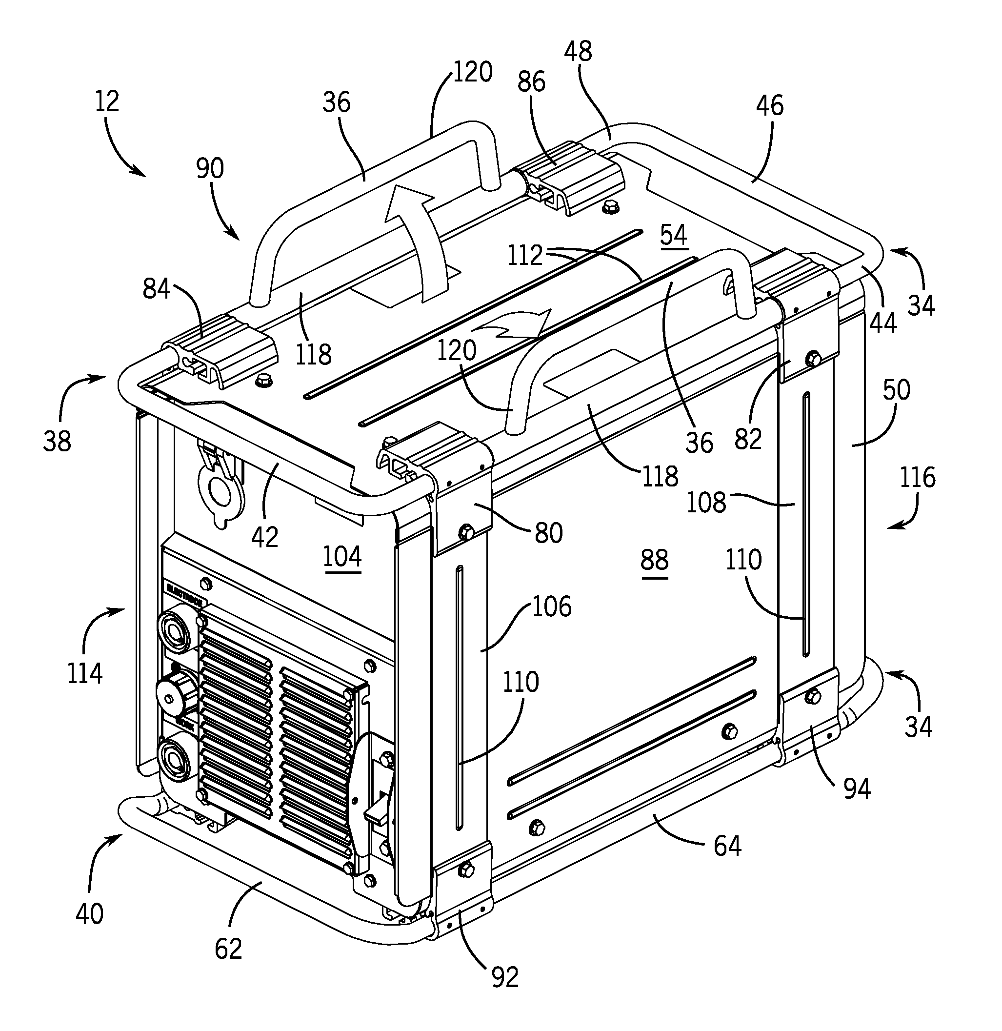
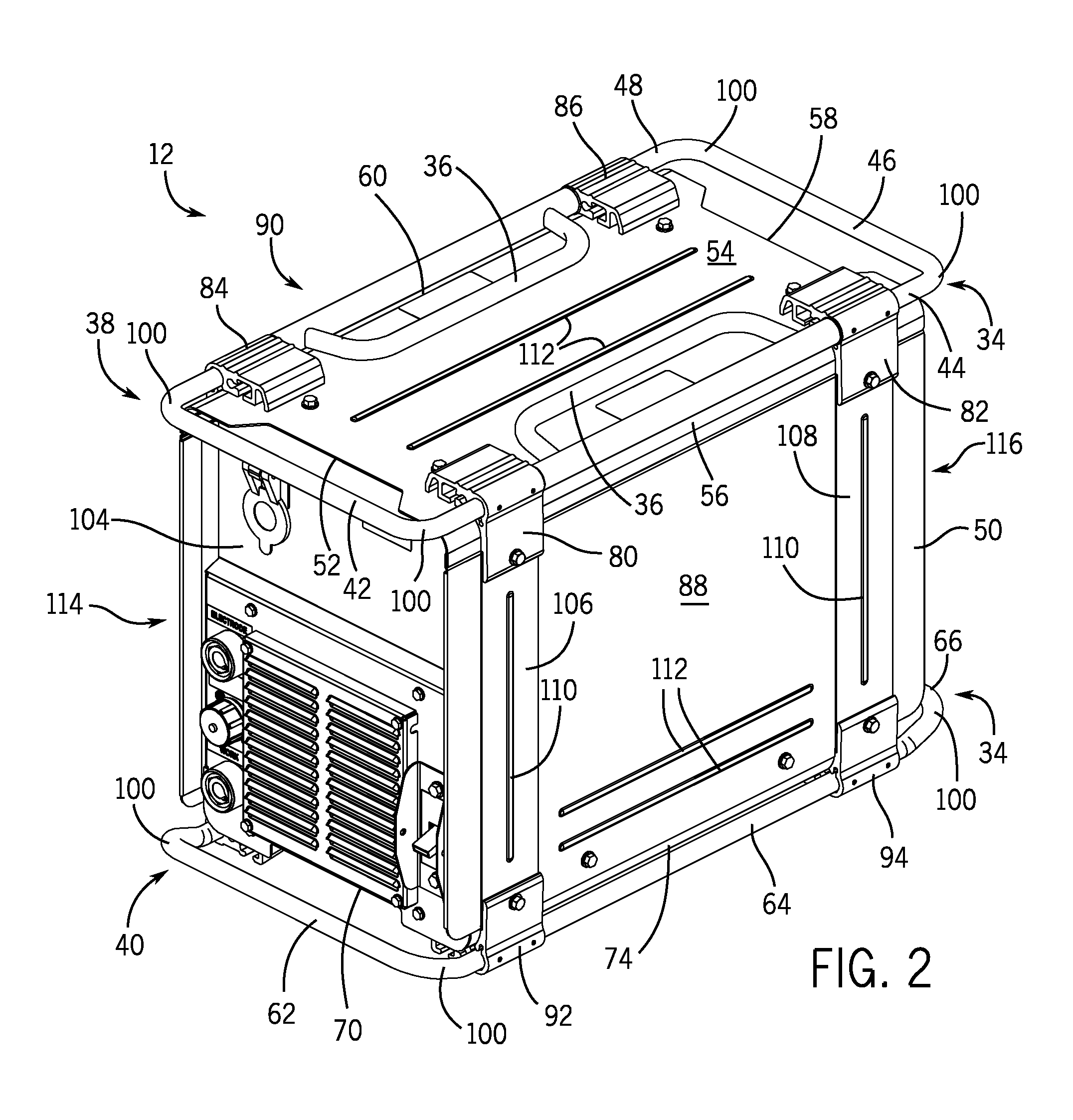
[0018]As described in greater detail below, in certain embodiments, a welding power supply unit includes a roll cage assembly with incorporated lift handles. As described above, welding power supply units are often subject to excessive handling and transportation requirements. The embodiments described herein address these concerns by providing a welding power supply unit capable of withstanding more abuse than conventional welding power supply units. The roll cage assembly described herein protects the sheet metal enclosure and operator interface of the welding power supply unit. In addition, the roll cage assembly described herein includes a plurality of incorporated lift handles. In certain embodiments, these incorporated lift handles are constructed from the same materials (e.g., tubular aluminum) as the roll bars of the roll cage assembly. The roll cage assembly described herein also enhances the structural integrity of the enclosure of the welding power supply unit by, for exa...


PUM

PropertyMeasurementUnit
non-orthogonal angleaaaaaaaaaa
poweraaaaaaaaaa

Abstract

A welding power supply unit includes an outer enclosure having a plurality of sides that encompass internal components of the welding power supply unit. The welding power supply unit also includes a roll cage assembly having a plurality of roll bars. Each roll bar is disposed generally parallel with, but not adjacent to, an edge of a side of the outer enclosure and external to the outer enclosure. At least two of the roll bars are associated with handle portions that rotate with respect to the respective roll bar. Each handle portion includes an extruded tubular aluminum bracket or a die cast aluminum bracket disposed around its respective roll bar. In addition, the welding power supply unit includes a plurality of fastening mechanisms attached to the outer enclosure, the fastening mechanisms securing the roll cage assembly to the outer enclosure.

Description

CROSS-REFERENCE TO RELATED APPLICATIONS[0001]This application is a Non-Provisional patent application of U.S. Provisional Patent Application No. 61 / 682,093, entitled “Welding Power Supply Roll Cage with Incorporated Lift Handles”, filed on Aug. 10, 2012, which is herein incorporated by reference in its entirety for all purposes.BACKGROUND[0002]The present invention relates generally to the field of welding systems, and more particularly to a welding power supply unit that includes a roll cage assembly with incorporated lift handles.[0003]Welding systems and power supplies are frequently used in harsh environments where they may be exposed to debris, dust, and other deposits that can harm or damage the welding power supplies. Similarly, common welding environments may include exposure to vibrating and mechanical tools, contact with which could damage a welding power supply. In addition, welding systems and power supplies are often subject to excessive handling and transportation requ...

Claims


Application Information

Patent Timeline
Patent Type & Authority Patents(United States)
IPC IPC(8): B23K37/00B62B3/10B62B3/16B23K37/02B23K9/32F02B63/04F16M3/00
CPCB23K37/00B23K9/32B23K37/0294B62B3/10B62B3/16F02B63/04F16M3/00
Inventor LIEBERT, SCOTT STEPHENDANTINNE, MARKUS MICHAEL
Owner ILLINOIS TOOL WORKS INC
Why Eureka
Try Eureka