Circuit system for redistribution of electrical energy in a vehicle

a technology of electrical energy and circuit system, which is applied in the direction of machines/engines, electric devices, machine/engine starters, etc., can solve the problems of high additional expenditure and high cost of achieving this single function, and achieve the effect of optimizing the level of expenditure, reducing fuel consumption, and reducing the size of dc/dc converters

Inactive Publication Date: 2015-10-06
ROBERT BOSCH GMBH
View PDF23 Cites 7 Cited by
  • Summary
  • Abstract
  • Description
  • Claims
  • Application Information

AI Technical Summary

Benefits of technology

[0014]With the aid of the example embodiment of the present invention, a topology for a vehicle electrical system which is optimized with regard to cost and efficiency is provided as a result of the provided circuitry of the electronic components of the circuit system, which includes a series connection of energy stores. Among other things, the requirement for increased recuperation power for recovering electrical energy, for providing an increased voltage for high-power consumers with the least possible variation in voltage, and an increase in the efficiency in nonrecuperation mode may be met with the aid of the circuit system. It is thus possible to implement a topology for a vehicle electrical system which is optimized with regard to a cost-to-performance ratio and which is able to meet requirements for future vehicle electrical systems.
[0016]In the further development of topology proposals as a result of the specialized circuitry of the DC / DC converter, only a low power of the DC / DC converter is necessary, even for high vehicle electrical system loads. Furthermore, an additional benefit for start-stop operation may be provided. With the aid of the circuitry of the DC / DC converter provided within the scope of the present invention, it is possible to minimize the size of the DC / DC converter. In addition, reduction in fuel consumption is also possible as a result of the provided energy supply of the vehicle electrical subsystems.
[0017]The embodiment of the present invention represents a circuit topology and operating strategy via which multiple savings approaches may be met while optimizing the level of expenditure. This results, among other things, in an increased generator voltage for increasing the generator efficiency. In coasting mode, when at least one of the electrical energy stores is charged, a recuperation potential may be increased in order to use the stored energy at a later time for assisting the vehicle electrical system. Assistance of the vehicle electrical system in start-stop operation is likewise possible. Thus, when the engine is restarted after a red traffic light, the voltage dip generated by the starter is compensated for on the vehicle electrical system side by the DC / DC converter. With the aid of the present invention it is likewise possible to meet possible requirements regarding protection against polarity reversal of the base vehicle electrical system battery. Furthermore, high-current consumers may be supplied at a higher voltage potential. A topology approach for an efficiency-optimized motor vehicle electrical system may be implemented with the aid of the present invention.

Problems solved by technology

Because an ultracapacitor has a very large number of serial cells in order to achieve the high voltage, and a DC / DC converter is designed for coupling the main vehicle electrical system to the vehicle-power supply system with variable voltage for providing a power P which is generally greater than 1.5 kW, the mentioned modules result in high costs.
However, this has limitations due to the greatly fluctuating voltage, which is low prior to the recuperation and is subsequently high.
However, the additional expenditure for achieving this single function is relatively high.

Method used


Image

  • Circuit system for redistribution of electrical energy in a vehicle
  • Circuit system for redistribution of electrical energy in a vehicle
  • Circuit system for redistribution of electrical energy in a vehicle

Examples


Embodiment Construction

[0026]The present invention is schematically illustrated in the figures based on specific embodiments, and is described in greater detail below with reference to the figures.

[0027]The figures are described in an interrelated and all-encompassing manner, with identical components being denoted by the same reference numerals.

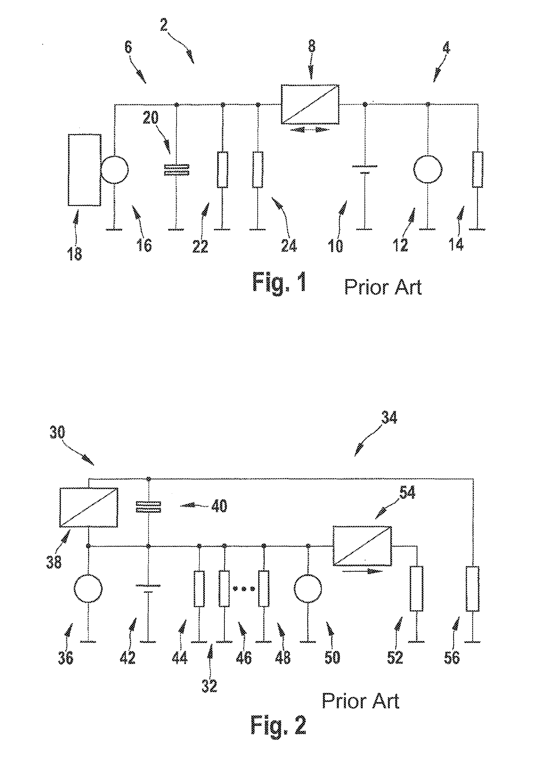
[0028]Conventional vehicle electrical system 2, schematically illustrated in FIG. 1, includes a main vehicle electrical system 4 which is designed for an operating voltage of 14 V, and a vehicle power supply system 6, which in the present case is designed for an operating voltage of 14 V to 42 V. Main vehicle electrical system 4 and vehicle power supply system 6 are connected to one another via a DC / DC converter 8.

[0029]In the present vehicle electrical system 2, it is provided that main vehicle electrical system 4 has a battery 10, a starter 12, and further consumers 14. Vehicle power supply system 6 includes a generator 16 which is associated with a regulating d...


PUM


Abstract

A circuit system for a vehicle electrical system, including a base vehicle electrical system having an energy store, a vehicle power supply system having an additional energy store, and a DC / DC converter. The energy store and the additional energy store are connected in series, and the DC / DC converter is provided for coupling between the base vehicle electrical system and the vehicle power supply system. A method for operating a vehicle electrical system is also described.

Description

FIELD OF THE INVENTION[0001]The present invention relates to a circuit system for a vehicle electrical system, and a method for operating a vehicle electrical system.BACKGROUND INFORMATION[0002]For vehicle electrical system topologies, conventional variants having multivoltage generators, i.e., variable-voltage generators, and downstream double-layer capacitors (DLC) or ultracapacitors (UCAP) are designed for a variable voltage level greater than 14 V, generally 30 V to 40V.[0003]It is thus possible to increase the peak performance of the vehicle electrical system, typically for optimizing the recovery of electrical energy, i.e., the recuperation capacity. This is achieved by increasing the maximum generator power at fairly high voltage, and providing one of the mentioned capacitors as a recuperation store with increased capability for peak charge acceptance. Because an ultracapacitor has a very large number of serial cells in order to achieve the high voltage, and a DC / DC converter...

Claims


Application Information

Patent Timeline
Patent Type & Authority Patents(United States)
IPC IPC(8): B60L1/00H02J1/08B60R16/03H02J7/14H02J1/00
CPCB60R16/03H02J1/08H02J7/1423H02J2001/008F02N11/0866F02N2011/0885F02N2011/0888H02J1/082H02J2310/46Y02T10/70
Inventor PISCHKE, ULFDRAESE, NILS
Owner ROBERT BOSCH GMBH
Why Eureka
Try Eureka