
Illuminated hand-held road sign

a hand-held and road sign technology, applied in the direction of advertising, ways, display means, etc., can solve the problems of inability to meet the needs of a single user, inability to and large number of complex devices, etc., to facilitate easy and compact storage, facilitate the use of such a use, and effectively direct and control traffic

Inactive Publication Date: 2015-10-06
CURTISS MICHAEL
View PDF13 Cites 9 Cited by
  • Summary
  • Abstract
  • Description
  • Claims
  • Application Information

AI Technical Summary

Benefits of technology

The patent text describes a handle that allows for the use of the apparatus in two ways: freestanding and hand-held. The handle has a two-base system that enables easy switching between the two modes. When used in a hand-held manner, the handle is securely inserted into a first base to allow for free rotation. In a freestanding manner, the handle is inserted into a second base, which has support legs that hold the apparatus upright and allow for free rotation. The support legs are foldable for easy storage when not in use. The power source and control equipment inside the handle can be used to illuminate the sign panel as desired. The handle also has a battery compartment door that can be accessed to replace the rechargeable battery.

Problems solved by technology

Personnel directing traffic is an inherently dangerous activity, especially if conducted at night or in low light level conditions.
Complex, heavy devices are expensive and unwieldy.
Furthermore, many complex devices are not suitable for a single user.

Method used


Image

  • Illuminated hand-held road sign
  • Illuminated hand-held road sign
  • Illuminated hand-held road sign

Examples


Embodiment Construction

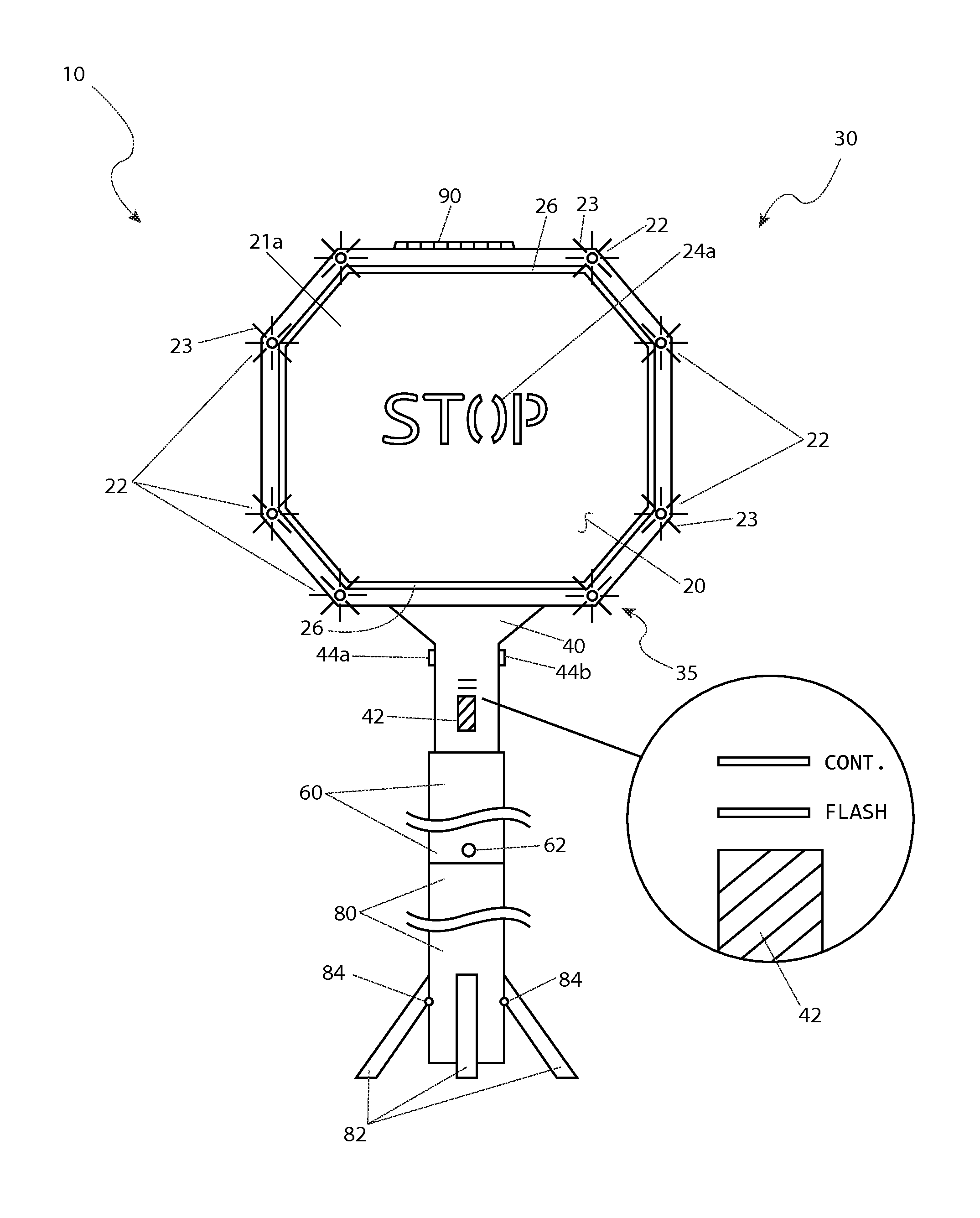
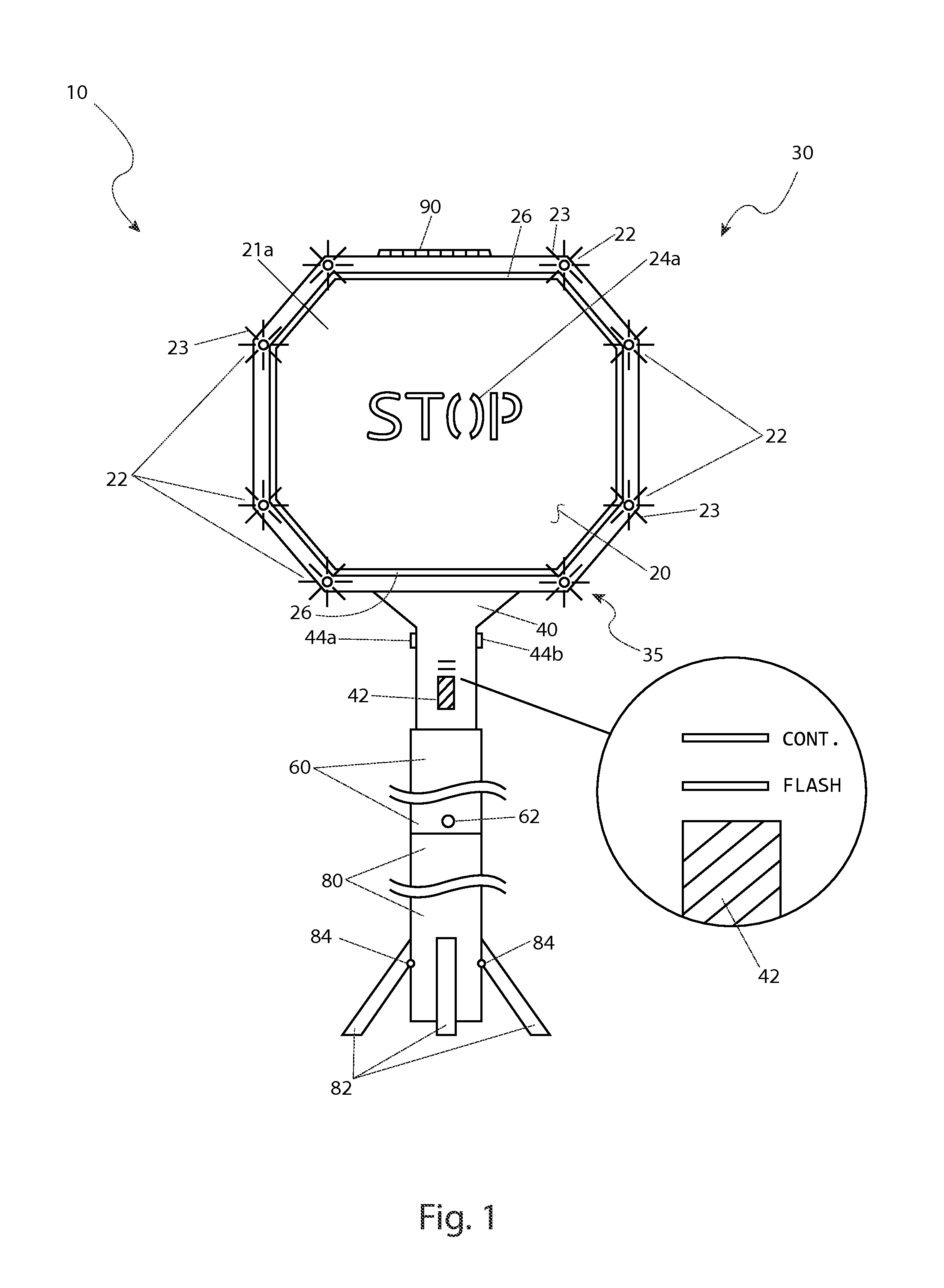
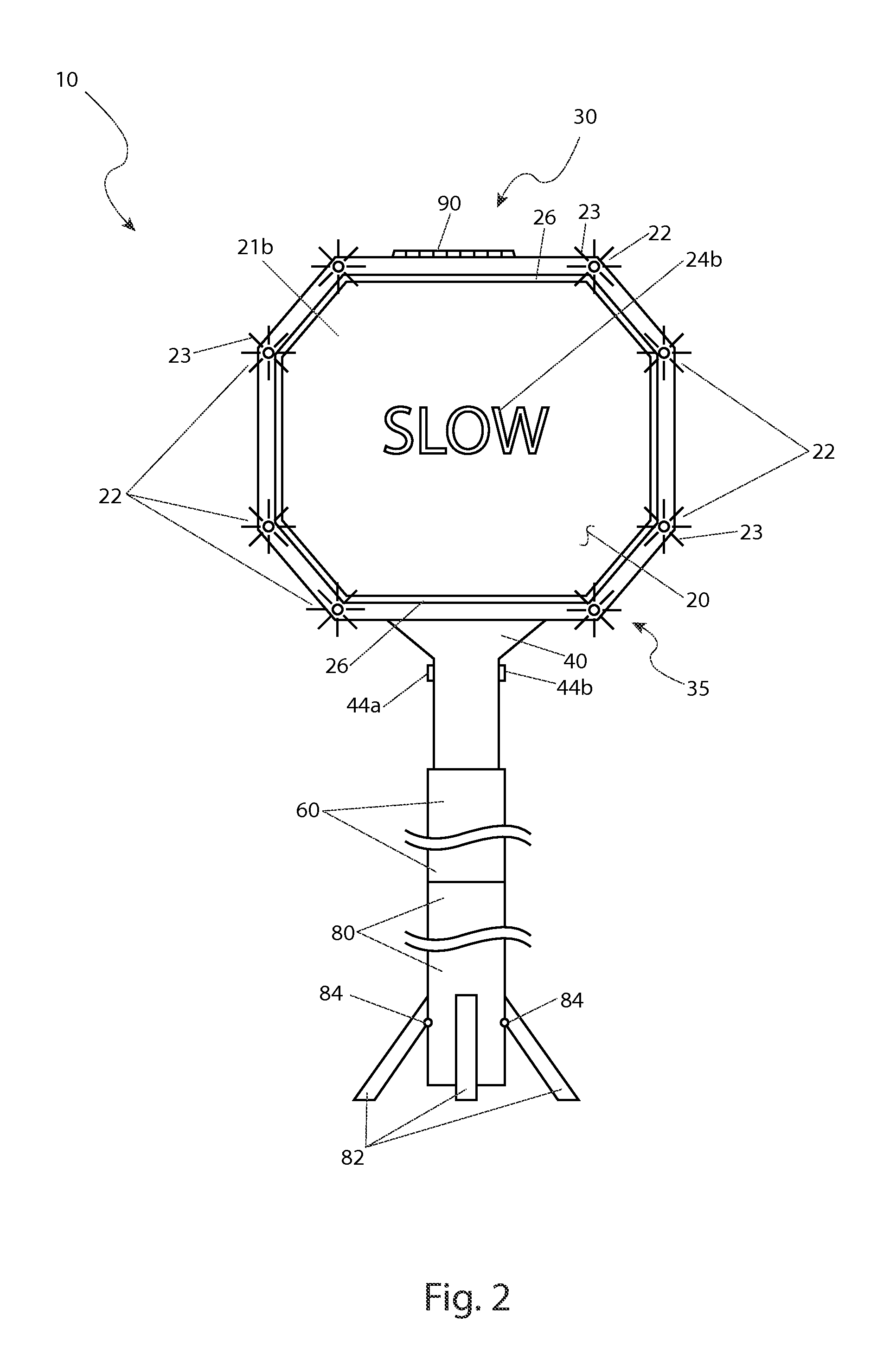
[0047]The best mode for carrying out the invention is presented in terms of its preferred embodiment, herein depicted within FIGS. 1 through 5. However, the invention is not limited to the described embodiment and a person skilled in the art will appreciate that many other embodiments of the invention are possible without deviating from the basic concept of the invention, and that any such work around will also fall under scope of this invention. It is envisioned that other styles and configurations of the present invention can be easily incorporated into the teachings of the present invention, and only one particular configuration shall be shown and described for purposes of clarity and disclosure and not by way of limitation of scope.

[0048]The terms “a” and “an” herein do not denote a limitation of quantity, but rather denote the presence of at least one of the referenced items.

[0049]Referring now to FIGS. 1 through 3, views of first side surface 21a and second side surface 21b po...


PUM


Abstract

An illuminated road sign has reflective lettering on each side, a plurality of illumination devices, and a battery-powered controller. The illumination devices are arranged along the perimeter of each face of the sign, are powered by the battery or with solar cell in an alternate embodiment, and are controlled by switches located on the handle of the sign assembly. The sign may be supported by a tripod structure portion that enables the sign to be utilized in a stand-alone state.

Description

RELATED APPLICATIONS[0001]The present invention was first described in and claims the benefit of U.S. Provisional Application No. 61 / 700,002, filed Sep. 12, 2012, the entire disclosures of which are incorporated herein by reference.FIELD OF THE INVENTION[0002]The present invention relates to a hand-held road sign further having an illumination means located thereon.BACKGROUND OF THE INVENTION[0003]Construction on roads is a common occurrence. Sometimes, the construction needs to be performed on roads that are still in use. The most common method of doing this is to block off part of the road and provide traffic control. The traffic control is most commonly conducted by a pair of construction personnel communicating together to allow traffic to flow on one (1) side and halting traffic on the other, then reversing this action as required. The use of hand-held signs, usually indicating “STOP” and “SLOW” on reversible sides, accomplishes this task. Personnel directing traffic is an inhe...

Claims


Application Information

Patent Timeline
Patent Type & Authority Patents(United States)
IPC IPC(8): G09F21/02G09F13/00
CPCG09F13/005G08B5/006E01F9/617G09F13/0463G09F13/0472
Inventor CURTISS, MICHAEL
Owner CURTISS MICHAEL
Learn More