Load control device having an electrically isolated antenna

a control device and antenna technology, applied in the direction of disturbance protection, high frequency circuit adaptation, printed capacitor incorporation, etc., can solve the problem of high cost of prior art isolation techniques, and achieve the effect of increasing the reception rang

Active Publication Date: 2015-10-06
LUTRON TECH CO LLC
View PDF31 Cites 20 Cited by
  • Summary
  • Abstract
  • Description
  • Claims
  • Application Information

AI Technical Summary

Benefits of technology

[0006]According to an embodiment of the present invention, a load control device is operable to control the amount of power delivered to a load from an AC power source. The load control device includes a printed circuit board that has a first layer comprising a first trace and a second layer comprising a second trace. The first and second traces being positioned parallel to one another. The load control device includes an enclosure that contains the printed circuit board. The load control device also includes a communication circuit that is electrically coupled to the first trace; and a wire monopole antenna that is electrically coupled to the second trace. The wire monopole antenna is adjustable into one or more positions. A first position of the one or more positions includes the wire monopole antenna extending freely from the enclosure. The first position increases a range of reception of the wire monopole antenna relative to the wire monopole antenna not extending freely from the enclosure. The first trace is oriented to form a capacitive coupling with respect to the second trace, such that the antenna is capacitively coupled to the communication circuit.
[0007]According to another embodiment of the present invention, a message receiving structure can be used in a load control device. The load control device has an enclosure containing the printed circuit board. The message receiving structure includes a printed circuit board having a first layer comprising a first trace, a second layer comprising a second trace, a third layer comprising a third trace, and a fourth layer comprising a fourth trace. The first, second, third, and fourth traces are positioned parallel to one another. The second trace is positioned between the first and third traces, and the third trace is positioned between the second and fourth traces. The message receiving structure includes a communication circuit that is electrically coupled to the first and third traces; and a wire monopole antenna electrically coupled to the second and fourth traces. The first and third traces are oriented to form a capacitive coupling with respect to the second and fourth traces, such that the antenna is capacitively coupled to the communication circuit. The wire monopole antenna is adjustable into one or more positions. A first position of the one or more positions includes the wire monopole antenna extending freely from the enclosure. The first position increases a range of reception of the wire monopole antenna relative to the wire monopole antenna not extending freely from the enclosure.

Problems solved by technology

The use of isolation transformers or optocouplers are well known techniques that can be used to electrically isolate the AC power source from other elements of a load control device, however such prior art isolation techniques can be costly.

Method used


Image

  • Load control device having an electrically isolated antenna
  • Load control device having an electrically isolated antenna
  • Load control device having an electrically isolated antenna

Examples


Embodiment Construction

[0014]The foregoing summary, as well as the following detailed description of the preferred embodiments, is better understood when read in conjunction with the appended drawings. For the purposes of illustrating the invention, there is shown in the drawings an embodiment that is presently preferred, in which like numerals represent similar parts throughout the several views of the drawings, it being understood, however, that the invention is not limited to the specific methods and instrumentalities disclosed.

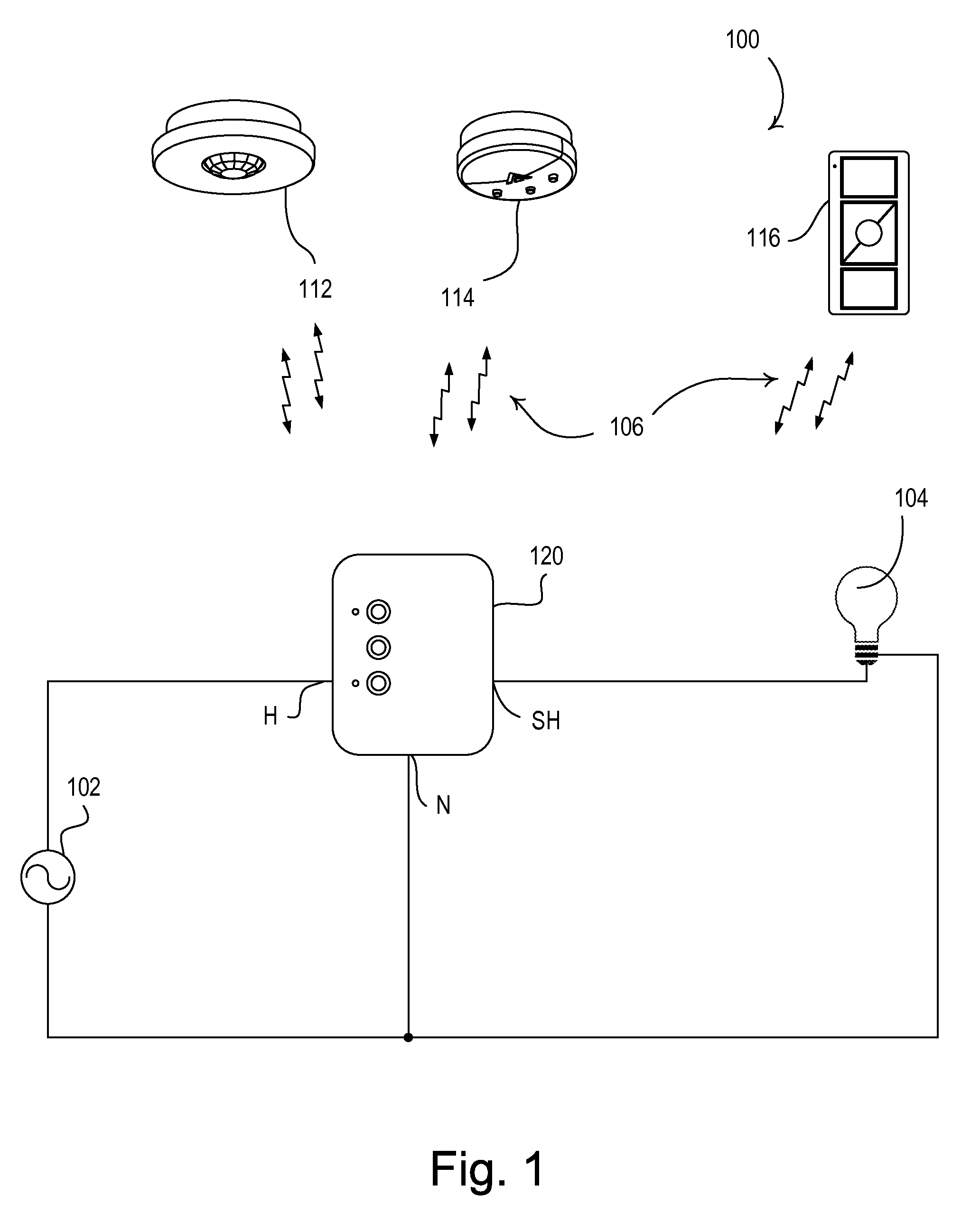
[0015]FIG. 1 is a simplified block diagram of a load control system 100 that may be installed in a building, such as a residence or a commercial space. The load control system 100 comprises a load control device 120 which is coupled to an alternating current (AC) power source 102 via hot (H) and neutral (N) terminals and is operable to control the power delivered to a lighting load 104 via a switched hot (SH) terminal. The load control device 120 may be operable to switch (i.e.,...


PUM


Abstract

A load control device for controlling the power delivered from a power source to an electrical load includes an antenna and a communication circuit to receive and transmit messages via radio frequency (RF) signals. The communication circuit is coupled to the power source but is capacitively coupled to the antenna. The capacitive coupling is formed through multiple layers of a printed circuit board (PCB) in which each layer includes a conductive trace that neighbors another conductive trace on an adjacent layer. The capacitive coupling provides that the antenna is electrically isolated from the communication circuit which accordingly, provides that the antenna is electrically isolated from the power source.

Description

CROSS-REFERENCE TO RELATED APPLICATIONS[0001]This application is a non-provisional application of commonly-assigned U.S. Provisional Application No. 61 / 485,962, filed May 13, 2011, entitled LOAD CONTROL DEVICE HAVING AN ISOLATED ANTENNA, the entire disclosure of which is hereby incorporated by reference.BACKGROUND OF THE INVENTION[0002]1. Field of the Invention[0003]The present invention relates to a load control device for control of the amount of power delivered from an alternating-current (AC) power source to an electrical load, and more particularly, to a load control device having a radio-frequency (RF) communication circuit to receive RF messages wherein the communication circuit includes an antenna which is electrically isolated from the AC power source.[0004]2. Description of the Related Art[0005]Typical load control devices are operable to control the amount of power delivered to an electrical load, such as a lighting load or a motor load, from an alternating-current (AC) p...

Claims


Application Information

Patent Timeline
Patent Type & Authority Patents(United States)
IPC IPC(8): H02H11/00H05B37/02H01Q1/00H01Q1/22H05K1/02H05K1/16
CPCH05B37/0272H01Q1/002H01Q1/007H01Q1/2216H05K1/0239H05K1/162H05B47/19
Inventor BARAGONA, ROBERTBLAKELEY, MATTHEW ROBERTBOLLINGER, JR., ROBERTTUNCAY, ORBAY
Owner LUTRON TECH CO LLC
Why Eureka
Try Eureka