Positioning device for bone drilling

a positioning device and bone technology, applied in bone drill guides, medical science, surgery, etc., can solve the problems of inability to accurately control the quality of surgery, inability to drill the hole at the accurate position, in the accurate direction, and in the accurate oblique angl

Inactive Publication Date: 2015-10-13
LIN HSIEH HSING
View PDF6 Cites 15 Cited by
  • Summary
  • Abstract
  • Description
  • Claims
  • Application Information

AI Technical Summary

Benefits of technology

[0013]The main objective of the invention is to provide a positioning device for bone drilling. The positioning device can mutually combine with and position a guide mold for simplified manufacture and easy operation.
[0015]When using the positioning device, the doctor can use the positioning block to fix the positioning device on a guide mold. A relative position between the positioning device and the guide mold can be relatively fixed. During or prior to bone drilling, the doctor can replace the positioning device with another positioning device with a more suitable diameter, oblique angle, and oblique direction so that the positioning device for bone drilling of the present invention can drill a hole at an accurate position, at an accurate oblique angle, and in an accurate oblique direction as desired.

Problems solved by technology

As accuracy, safety and reliability of a surgery rely crucially on the clinical experience of the doctor, a less experienced doctor may not be able to fully control the quality of surgery.
However, the conventional positioning devices are simply placed in the notch of the guide mold without any design or mechanism to be fixed on the guide mold, so relative displacement between the conventional positioning devices and the guide mold frequently occurs.
Consequently, the dentist cannot drill the hole at the accurate position, at the accurate oblique angle, and in the accurate direction as preset.
However, when drilling a hole on a gum bone, sizes of the magnetic rod and the guiding panels are almost as large as a tooth, and the magnetic rod and the guiding panels thus have to be compactly designed.
If the conventional positioning devices further include the fixing hole and the fixing part protruding in the fixing hole, a manufacture of the conventional positioning devices becomes highly complicated.
Therefore, the conventional positioning devices still have to be improved.

Method used


Image

  • Positioning device for bone drilling
  • Positioning device for bone drilling
  • Positioning device for bone drilling

Examples


Embodiment Construction

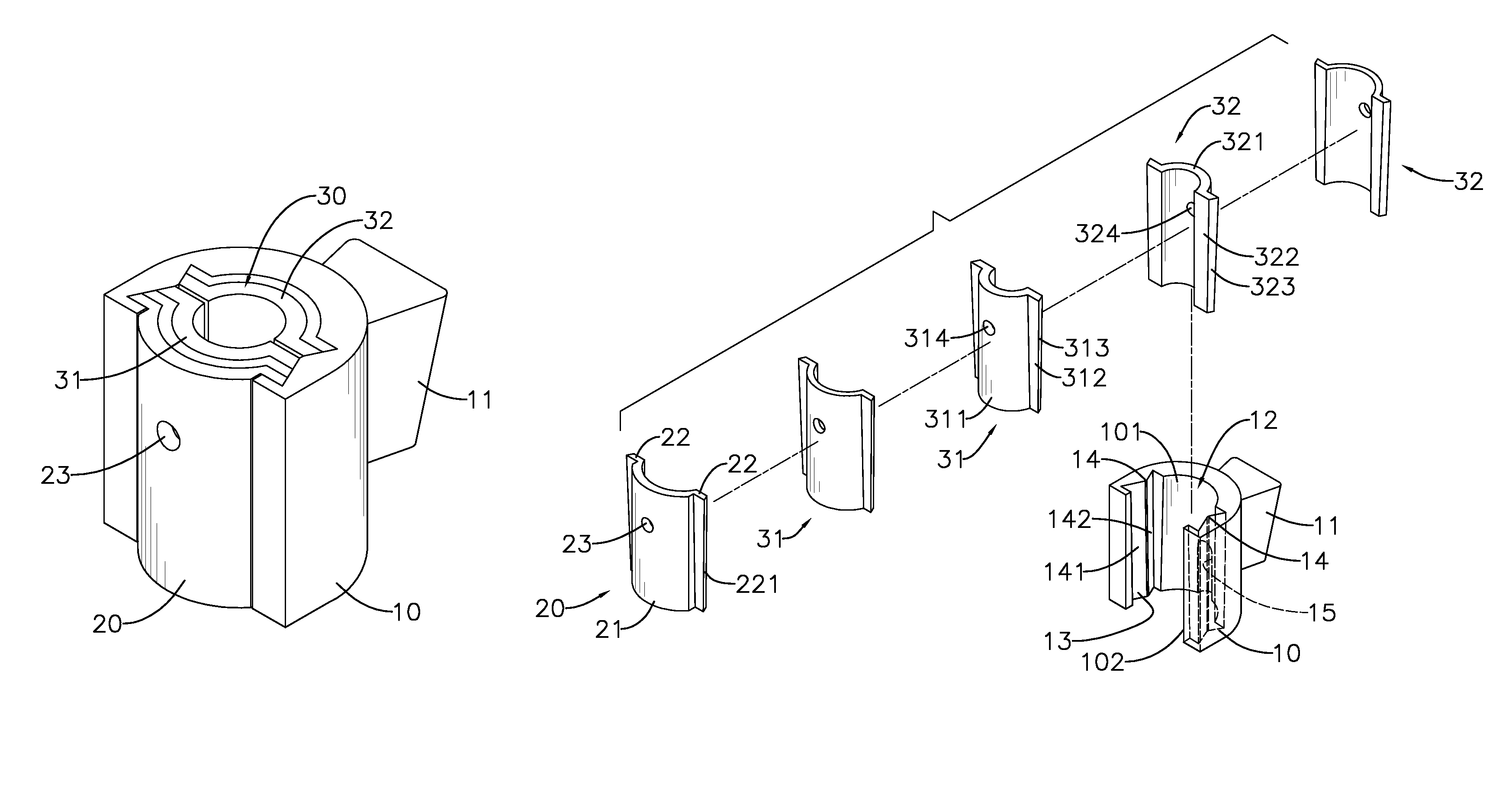
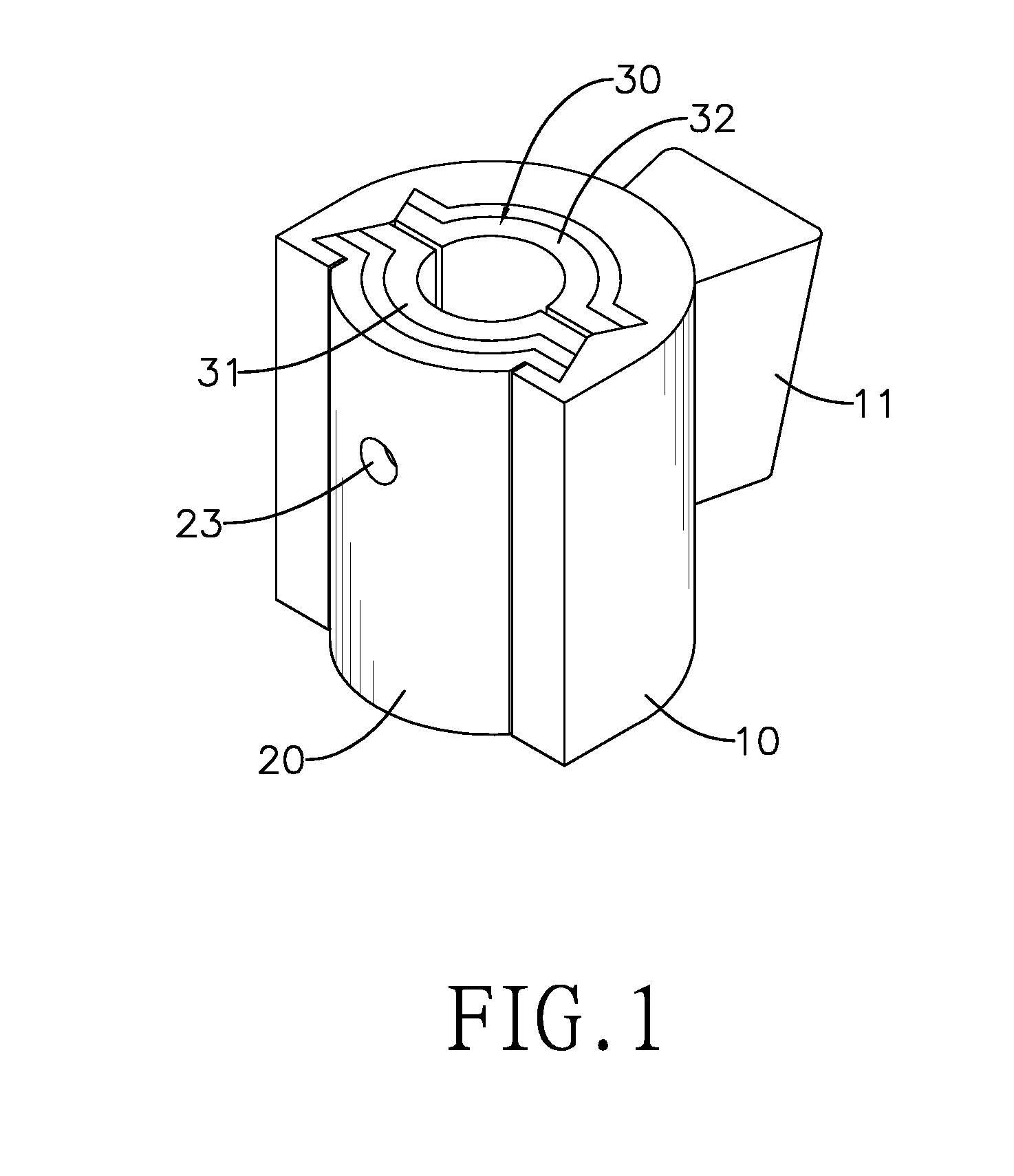
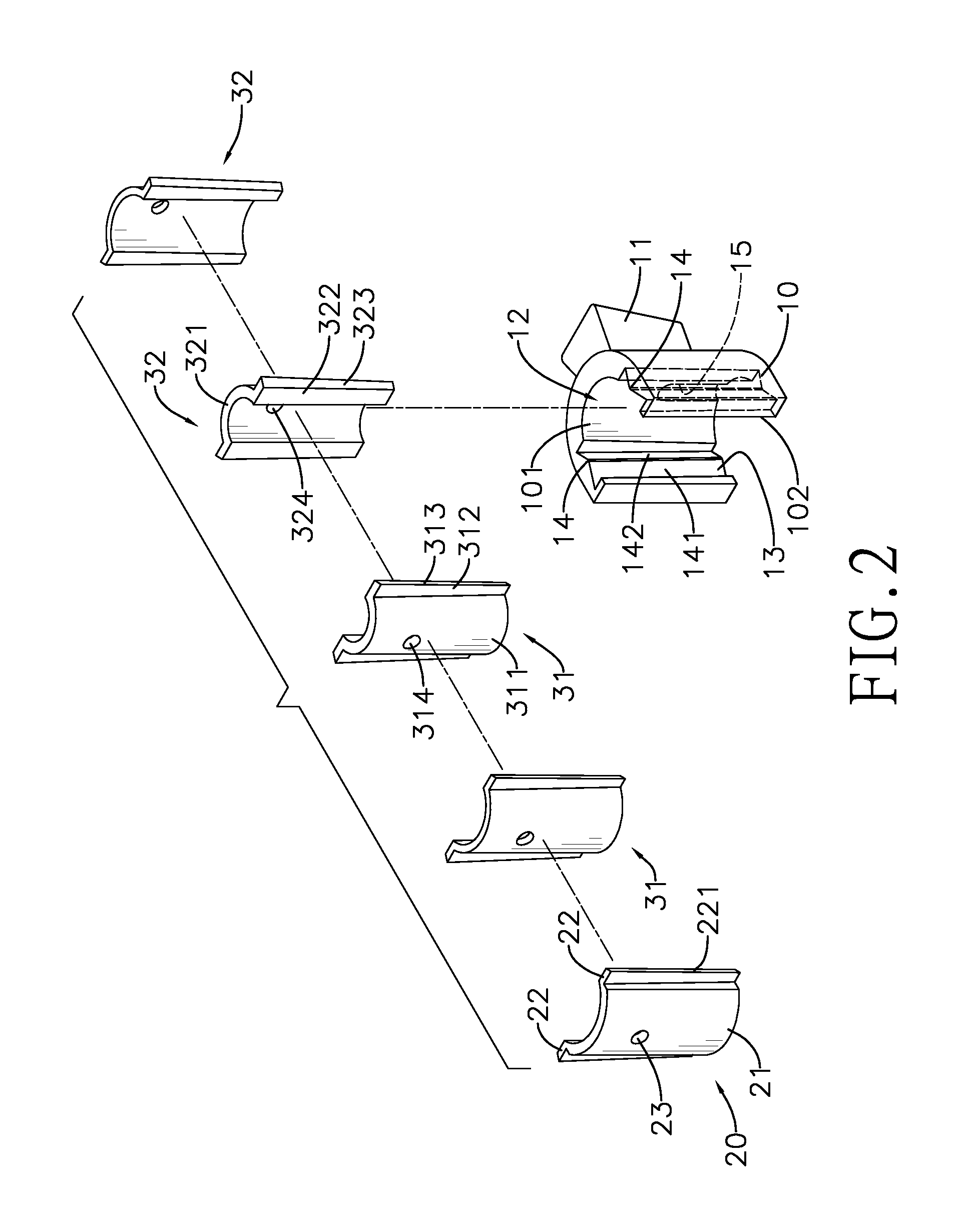
[0028]In a preferred embodiment as shown in FIGS. 1 and 2, a positioning device in accordance with the present invention comprises a base 10, an outer guiding panel 20 and at least one inner guiding panel set 30.

[0029]The base 10 has a semicircular cross section and comprises an outer wall, a positioning block 11, a guiding recess 12, an inner wall 101, two positioning recesses 13, two guiding protrusions 14 and a hook recess 15. The positioning block 11 is formed on the outer wall of the base 10. The guiding recess 12 is formed longitudinally through the base 10 and is formed through the outer wall of the base 10 to form a side opening 102. The inner wall 101 of the base 10 surrounds the guiding recess 12 and is a concave camber. The positioning recesses 13 are formed separately on the inner wall 101 of the base 10, and the positioning recesses 13 are formed through the ends of the base 10 and are opposite to each other. The guiding protrusions 14 are each respectively formed on a ...


PUM


Abstract

The positioning device for bone drilling comprises a base, and the base has an outer wall, a positioning block, a guiding recess and an inner wall. The positioning block is formed on the outer wall of the base. The guiding recess is formed longitudinally through the base. The inner wall surrounds the guiding recess and the inner wall is a concave camber. The doctor can use the positioning block to fix the positioning device on a guide mold. A relative position between the positioning device and the guide mold can be relatively fixed. Prior to or during the drilling, the doctor can replace the positioning device with another positioning device with a more suitable diameter, oblique angle and oblique direction so that the positioning device for bone drilling can drill a hole at an accurate position, at an accurate oblique angle and in an accurate oblique direction as desired.

Description

BACKGROUND OF THE INVENTION[0001]1. Field of the Invention[0002]The present invention relates to a positioning device for bone drilling, and more particularly to a positioning device for bone drilling or implantation.[0003]2. Description of Related Art[0004]In a conventional surgery method, a doctor plans the position and path of inversion according to an X-ray image or a computerized tomography of a patient's bone, as well as relying on the doctor's anatomy knowledge and clinical surgery experience. As accuracy, safety and reliability of a surgery rely crucially on the clinical experience of the doctor, a less experienced doctor may not be able to fully control the quality of surgery. Selection of position and angle of a bone screw implant is crucial so as to avoid hurting a nerve and a vein of a patient during a surgery, otherwise the patient may suffer from sequelae such as hemiplegia.[0005]For a dentist, when a patient's tooth is broken or missing, a normal treatment is to repla...

Claims


Application Information

Patent Timeline
Patent Type & Authority Patents(United States)
IPC IPC(8): A61B17/17A61C1/08
CPCA61C1/084A61B17/17A61B17/1757
Inventor LIN, HSIEH-HSING
Owner LIN HSIEH HSING
Why Eureka
Try Eureka