Eureka AIR delivers breakthrough ideas for toughest innovation challenges, trusted by R&D personnel around the world.

Flexible sander

Active Publication Date: 2015-10-13
FOSTER THOMAS E
View PDF36 Cites 5 Cited by
  • Summary
  • Abstract
  • Description
  • Claims
  • Application Information

AI Technical Summary

Benefits of technology

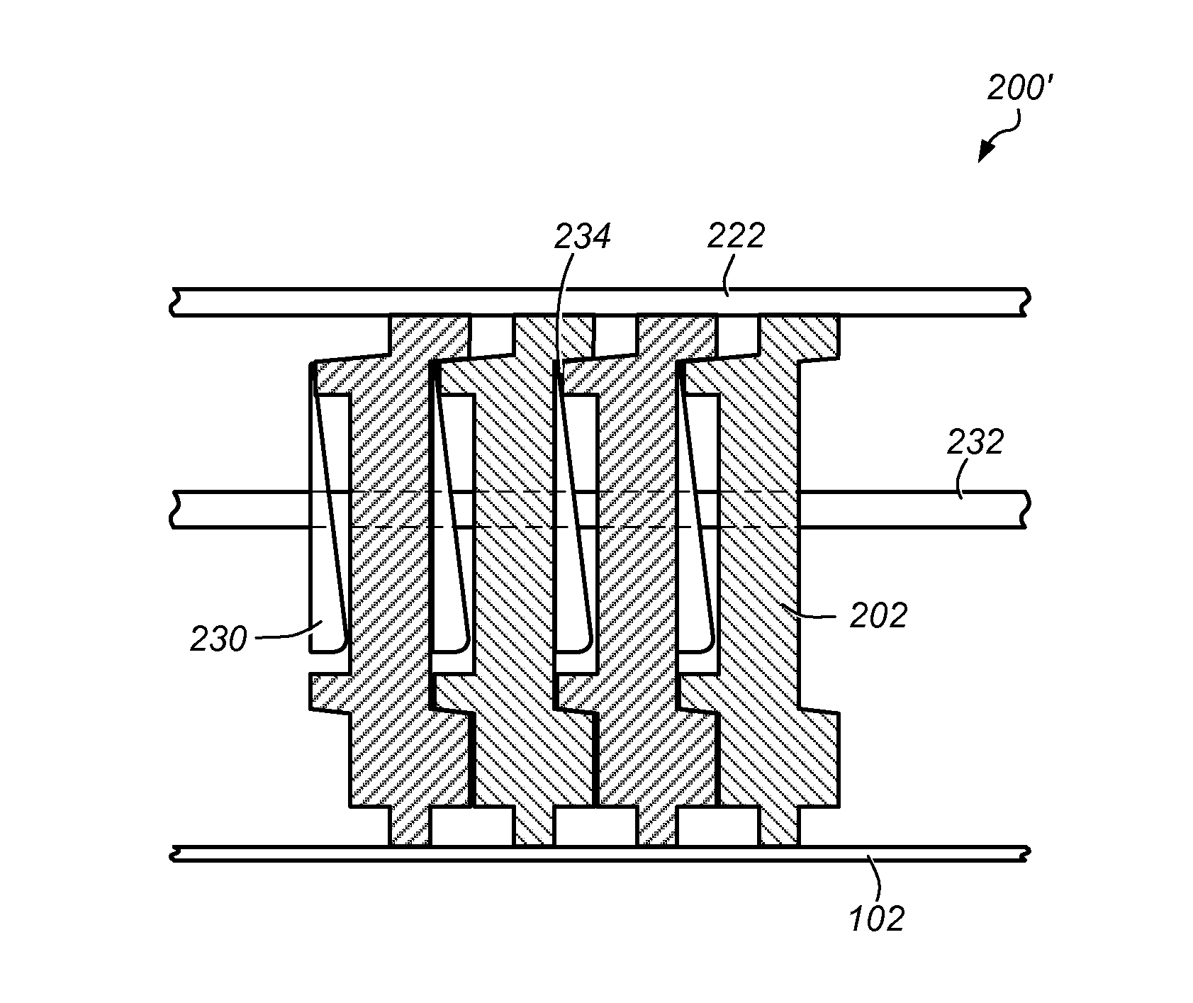
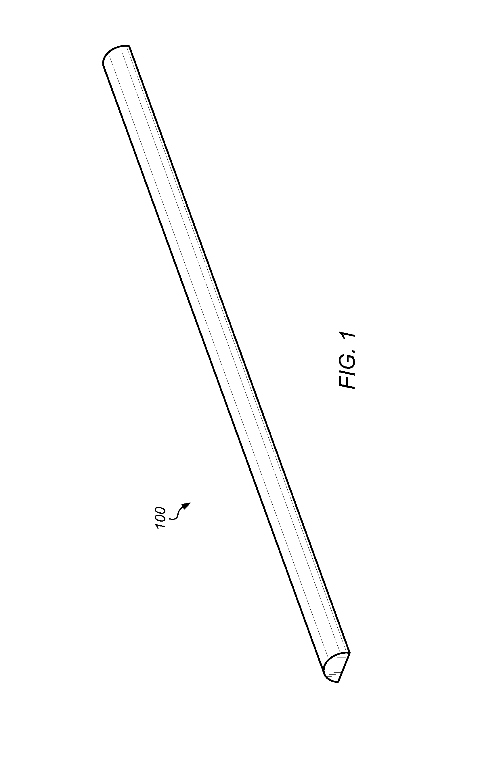
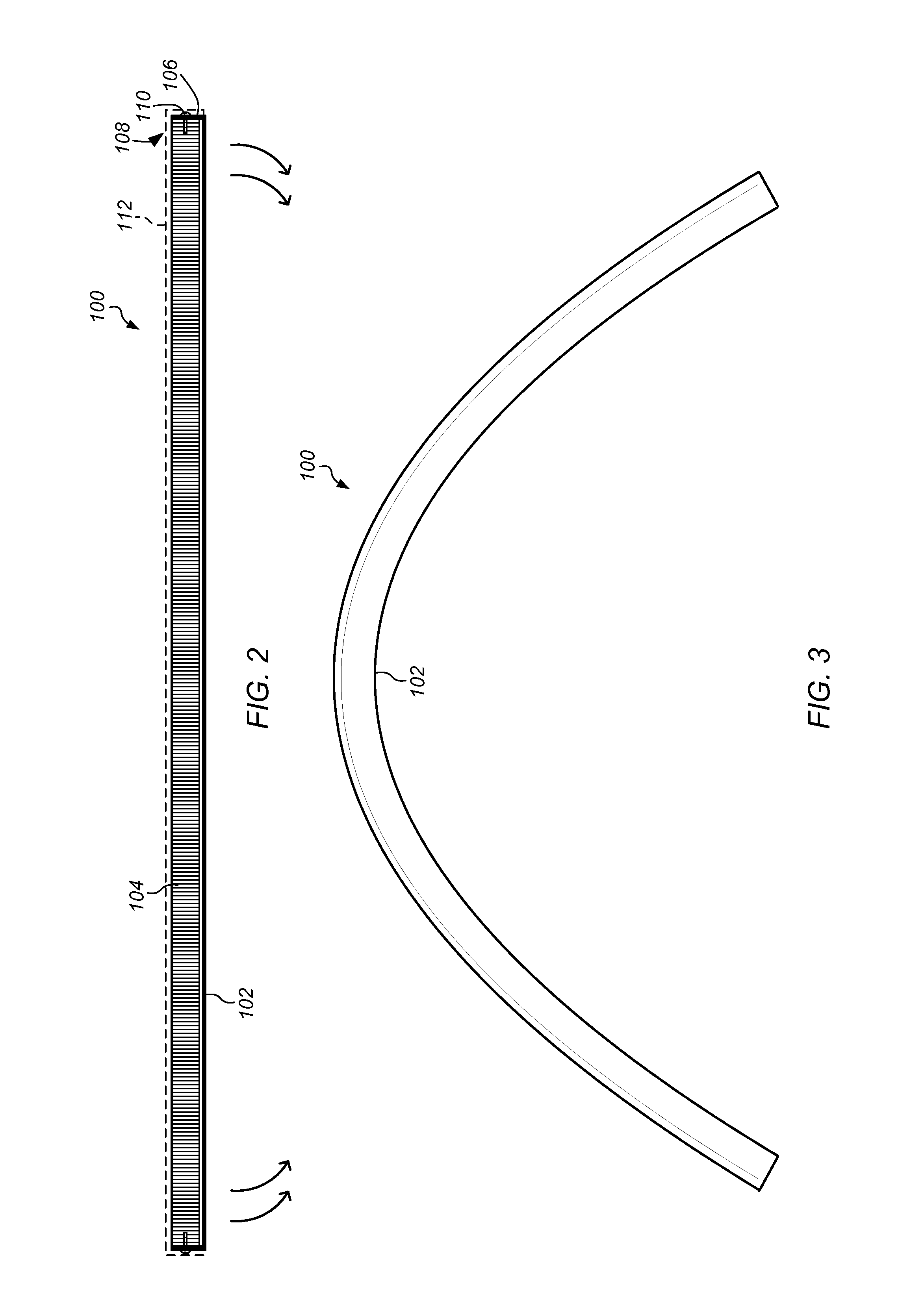
The patent describes a flexible sanding apparatus that includes a thin, flat spring member and multiple disc-shaped elements that are attached to one side of the spring member. These discs are stacked along the length of the spring member and can bend concave or convex depending on the desired effect. The apparatus also includes a cover to protect the discs and a sanding surface that can flex flexibly. The technical effects of this design are improved flexibility and control over the sanding surface, making it easier to achieve the desired effect.

Problems solved by technology

Flexing the foam rubber handle may, however, create build up in the handle because the top stretches as the handle is bent and the bottom portion does not compress since it is attached to a flat spring.
However, it may take significant pressure to bend the ends of the foam rubber handle down to curve the handle and the handle may have a limited amount of bend that prevents the handle from having the ability to work on smaller radius curves.
In addition, when high pressure is applied, the flexible sanding apparatus may not provide the desired arc because of the thickness and stiffness of the flexible sanding apparatus.
Providing high pressure substantially simultaneously to the ends may, however, be tiring to a user and not allow the user to have any “feel” for the contour of the body panel being worked on by the user.
Another problem with the flexible sanding apparatus described in U.S. Pat. No. 6,554,113 to Wheeler is that the foam rubber handle may bend backward (e.g., bend with the ends going away from the surface) when pressure is applied to the foam rubber handle.
Thus, when sanding a relatively flat surface, the low spots on the flexible sanding apparatus may be lower than desired, making it difficult to obtain a flat sanding surface.

Method used


Image

  • Flexible sander
  • Flexible sander
  • Flexible sander

Examples


Embodiment Construction

[0031]In the context of this patent, the term “coupled” means either a direct connection or an indirect connection (e.g., one or more intervening connections) between one or more objects or components. The phrases “attached” and “directly connected” mean a direct connection between objects or components such that the objects or components are connected directly to each other so that the objects or components operate in a “point of use” manner.

[0032]In the context of this patent, the term “automobile” refers to any type of motor vehicle such as a car, truck, or SUV. It is to be understood that while reference is made to the use of the sanding / spreading apparatus (e.g., “sander”) on surfaces of an automobile that the sanding / spreading apparatus may be used in many other instances. For example, the sander may be used on single or compound curved surfaces and may also be used to flatten surfaces. The sander may be used on any surface that can be sanded to smooth out imperfections or to ...


PUM


Abstract

A flexible sanding apparatus includes a thin, relatively flat spring member and a plurality of disc-shaped members attached to a first side of the flat spring member along a length of the flat spring member. The disc-shaped members may be horizontally stacked along the length of the flat spring member with at least one disc-shaped member at least partially contacting its adjacent disc-shaped members when the flat spring member lies flat. The disc-shaped members may be individually attached to the first side of the flat spring member along at least portions of outer edges of the disc-shaped members. A sanding surface may be coupled to a second side of the flat spring member.

Description

BACKGROUND[0001]1. Field of the Invention[0002]The present invention relates to a contour sander. More particularly, the invention relates to a flexible sander and / or spreader for use on single or compound curved surfaces and also can be used to flatten surfaces.[0003]2. Description of Related Art[0004]One of the more common uses of contour sanders is repairing automobile body panels. Automobile body panels are typically made of light-weight metals, fiberglass, or plastic materials that are relatively thin. The panels are shaped into contoured (curved) body lines to provide strength and aerodynamic features for the body panels. The contoured body lines may include convex or concave curves, scooped areas, and / or channels. The sanders used on the body panels may have an adjustable curvature to allow the sander to conform to different shaped body panels and allow the sander to be used on multiple body panels and / or automobiles. The curvature of the sander may be adjusted to conform to ...

Claims


Application Information

Patent Timeline
IPC IPC(8): B24B15/00B24D15/04
CPCB24D15/04
Inventor FOSTER, THOMAS E.
Owner FOSTER THOMAS E
Why Eureka
Eureka Blog
Learn More