Electromagnetic sensing touch screen

a touch screen and electromagnet technology, applied in the field of touch screens, to achieve the effect of reducing the intensity of the detection signal

Inactive Publication Date: 2015-10-13
NETIO TECH
View PDF7 Cites 136 Cited by
  • Summary
  • Abstract
  • Description
  • Claims
  • Application Information

AI Technical Summary

Benefits of technology

[0019]Therefore, the present invention can perform the finger detection process to correctly detect the location of the finger(s), and further determine how close the finger(s) approaches to the sensed capacitor matrix or whether the finger(s) touches the sensed capacitor matrix. The finger detection process preferably comprises the initialization operation and the detection operation.
[0021]In other words, the initialization operation is primarily intended to correct the whole touch process of the electromagnetic sensing touch screen according to the present invention so as to improve the stability and preciseness of the touch function.
[0023]Therefore, when the finger(s) is far away, the detection signal of the EM wave receive / detection unit has the maximum intensity, and as the finger(s) approaches, the intensity of the detection signal decreases. It is possible to confirm that the finger(s) approaches to or touches the sensed capacitor units by checking if the intensity of the detection signal decreases to a predetermine threshold, thereby implementing the correct finger detection operation for the multipoint touch and display function.

Problems solved by technology

Different sensing method can provide different application problems in final application environment, for example the Projected capacitance touch sensor will be affected by radio frequencies emissions that nearby the harmonic of PCT touch sensor scanning frequency, the touch controller may report false information cause by the radiate radio noise.

Method used


Image

  • Electromagnetic sensing touch screen
  • Electromagnetic sensing touch screen
  • Electromagnetic sensing touch screen

Examples


Embodiment Construction

[0030]The present invention may be embodied in various forms and the details of the preferred embodiments of the present invention will be described in the subsequent content with reference to the accompanying drawings. The drawings (not to scale) show and depict only the preferred embodiments of the invention and shall not be considered as limitations to the scope of the present invention. Modifications of the shape of the present invention shall too be considered to be within the spirit of the present invention.

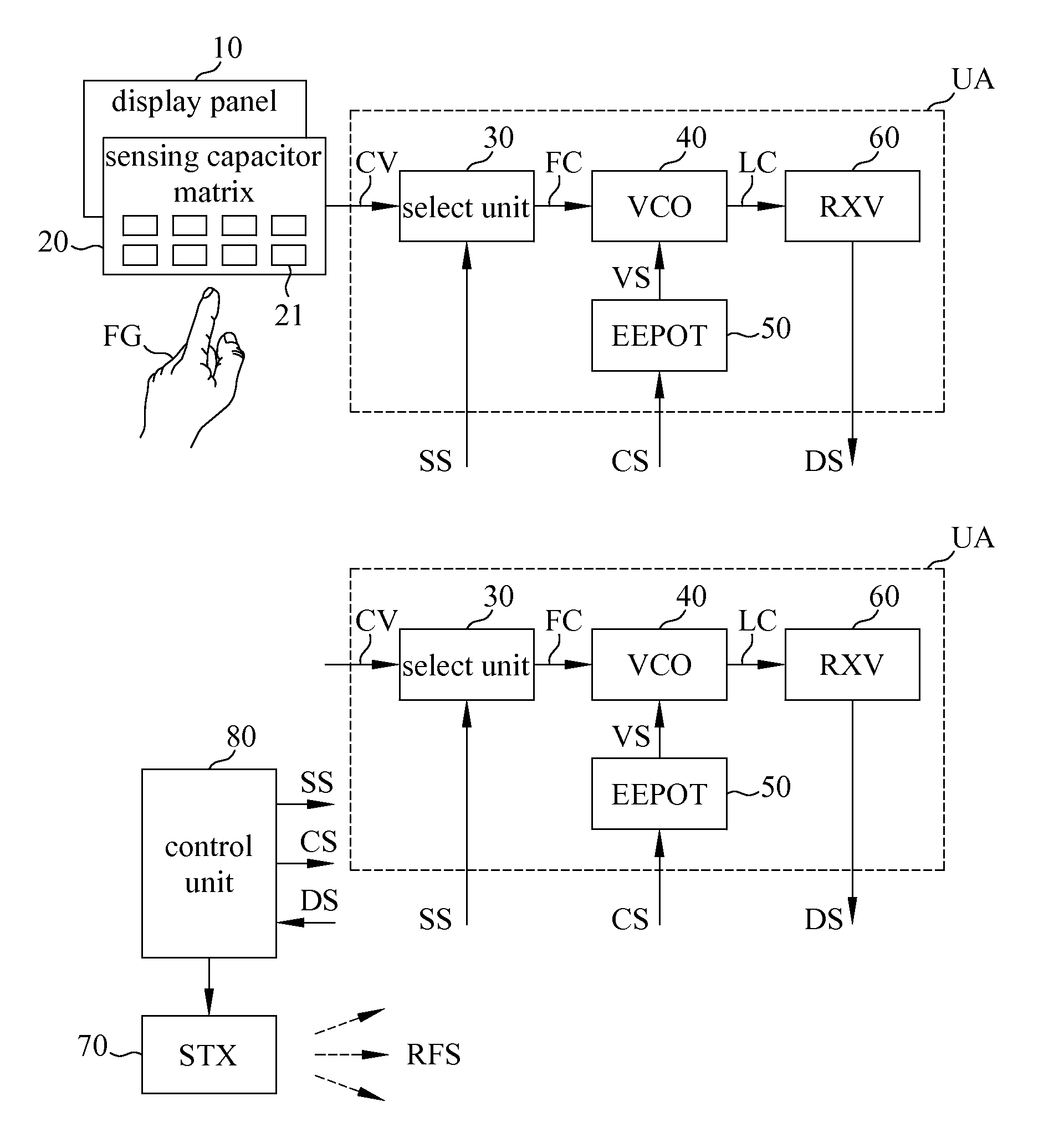
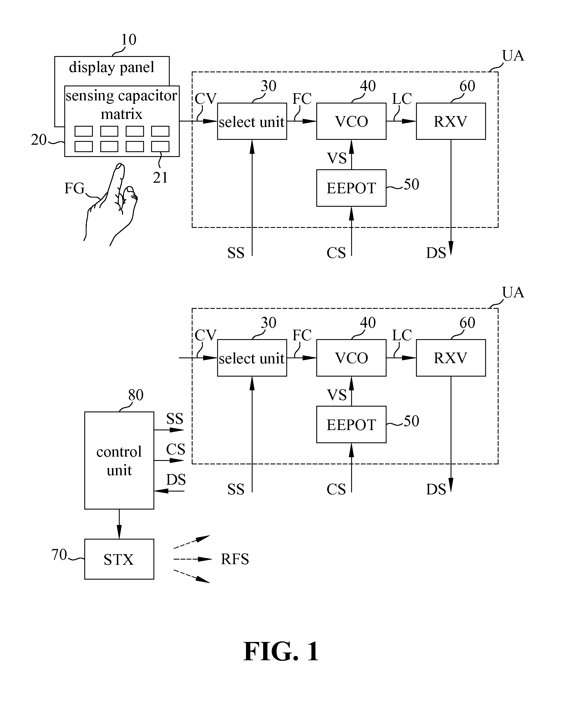
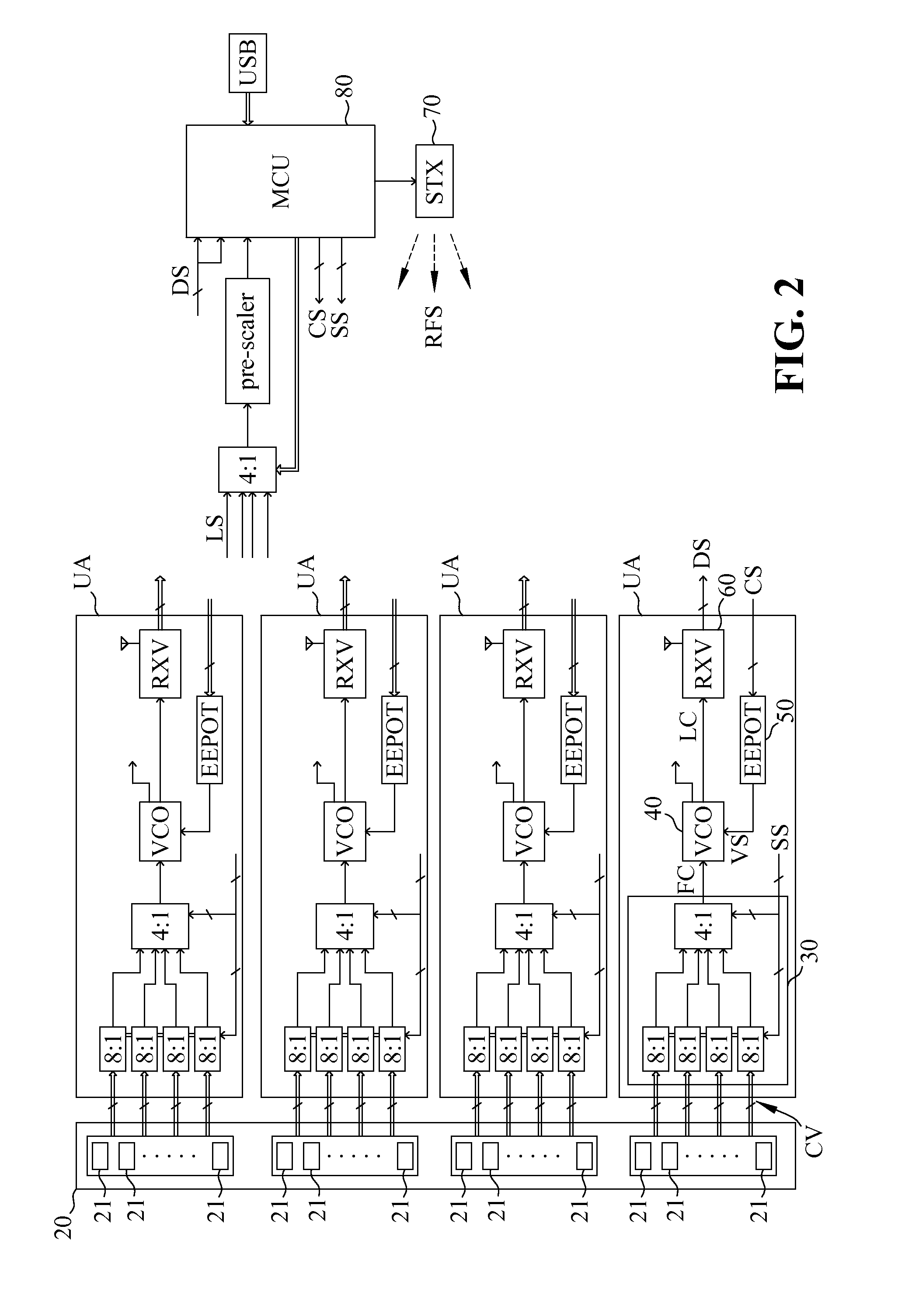
[0031]Please refer to FIG. 1 illustrating the electromagnetic sensing touch screen according to one of the embodiment of the present invention. As shown in FIG. 1, the electromagnetic sensing touch screen according to the present invention generally comprises a display panel 10, a sensing capacitor matrix 20, a plurality of select units 30, a plurality of voltage controlled oscillators (VCOs) 40, a plurality of digital potentiometers (EEPOT) 50, a plurality of EM (electroma...


PUM

PropertyMeasurementUnit
frequencyaaaaaaaaaa
transparencyaaaaaaaaaa
capacitanceaaaaaaaaaa

Abstract

The present invention discloses an electromagnetic sensing touch screen, which includes a display panel, a sensing capacitor matrix, select units, voltage controlled oscillators (VCOs), digital potentiometers, EM (electromagnetic) wave receive / detection units, a standard EM wave transmit unit and a control unit. A single detection unit consists of a corresponding select unit, VCO, digital potentiometer and EM wave receive / detection unit. The control unit drives the standard EM wave transmit unit to transmit standard EM wave, and further controls the EM wave receive / detection units to receive sensed capacitance values from the sensing capacitor matrix in a scanning manner. As a result, each EM wave receive / detection unit generates a respective detection signal for determining the location of the finger(s) and checking how the finger(s) approaches to or actually touches the sensing capacitor matrix, thereby generating finger location information and implementing the multipoint touch and display function.

Description

BACKGROUND OF THE INVENTION[0001]1. Field of the Invention[0002]The present invention generally relates to a touch screen, and more specifically to an electromagnetic sensing touch screen using the frequency drift of the specific electromagnetic wave to detect the finger(s) location and implement a function of multipoint touch and display.[0003]2. The Prior Arts[0004]Modern computers use graphic user interface as human to machine interaction, mouse, keyboard and touch screen are commonly used as input device. The touch screen can be constructed in many ways, and some typical examples of common technologies to build touch sensors are shown below:[0005]1. Resistive type touch sensor[0006]2. Surface capacitance[0007]3. SAW[0008]4. IR[0009]5. Projected capacitance[0010]Different sensing method can provide different application problems in final application environment, for example the Projected capacitance touch sensor will be affected by radio frequencies emissions that nearby the harm...

Claims


Application Information

Patent Timeline
Patent Type & Authority Patents(United States)
IPC IPC(8): G06F3/041G06F3/046G06F3/044G06F3/045H01F5/00G09B5/04G01B7/14G01B7/30
CPCG06F3/044G06F3/046G06F3/04166G06F3/0418
Inventor WANG, CHUN HSIAO
Owner NETIO TECH
Why Eureka
Try Eureka