Pressure detector

a detector and pressure technology, applied in the direction of fluid pressure measurement using elastically deformable gauges, instruments, mechanical elements, etc., can solve the problems of affecting and affecting the accuracy of pressure detection. , the effect of preventing the degradation of the detection accuracy of pressure sensors due to the temperature of fluid

Inactive Publication Date: 2015-10-20
SMC CORP
View PDF16 Cites 3 Cited by
  • Summary
  • Abstract
  • Description
  • Claims
  • Application Information

AI Technical Summary

Benefits of technology

[0012]A general object of the present invention is to provide a pressure detector that avoids a dead space therein that impedes the smooth flow of fluid, and which by preventing the influence of temperature changes of the fluid, enables pressure measurements of the fluid to be carried out with high accuracy.
[0014]According to the present invention, in the pressure detector, the pressure transmitting body is disposed displaceably in the through hole that communicates between the flow passage through which the fluid flows and the sensor chamber in which the pressure sensor is disposed. Further, one end of the pressure transmitting body extends in the through hole to an end on the side of the flow passage, and the one end is constantly exposed to the fluid. Thus, creation of a dead space in the through hole is prevented, pooling of liquid or generation of air bubbles due to such a dead space can reliably be prevented, and detection of pressure can be carried out with high precision. Further, since the pressure sensor can be disposed at a location distanced from the fluid, degradation of the detection accuracy of the pressure sensor due to the temperature of the fluid can be prevented, and detection of pressure with high accuracy can be performed.

Problems solved by technology

However, with the conventional technique disclosed in Patent Document 1, since the disk membrane is arranged in an upwardly offset position with respect to the hole portion through which the corrosive liquid flows, a dead space is created between the hole portion and the disk membrane.
Due to such dead spaces, smooth flowing of the fluid is hindered, and there is a concern that pooling of liquid or retention of debris or the like may occur within the dead space.
Further, it is easy for air bubbles (air) to become attached inside the dead space, so that collection of air due to such air bubbles tends to occur, and high precision measurement of pressure cannot be performed.
However, since flow passage resistance occurs in the fluid that flows through the curved portion, pressure loss tends to increase, and further, a sufficient flow rate cannot be assured.
Furthermore, with the pressure detectors disclosed in Patent Documents 1 through 3, the distance between the flow passage through which the fluid flows and the pressure sensor itself is extremely short, while in addition, since the pressure sensor is arranged and separated from the fluid merely by a disk membrane or a diaphragm or the like, for example, in the event there is a change in the temperature of the fluid, a concern exists that such a change may adversely influence the pressure measurement made by the pressure sensor.

Method used


Image

  • Pressure detector
  • Pressure detector
  • Pressure detector

Examples


first embodiment

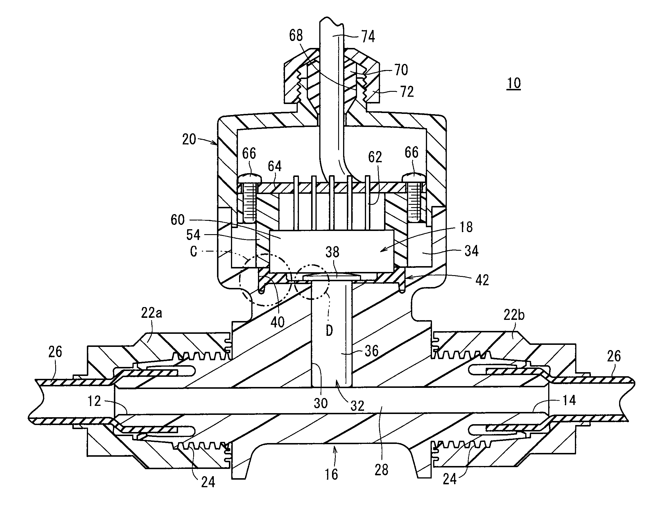
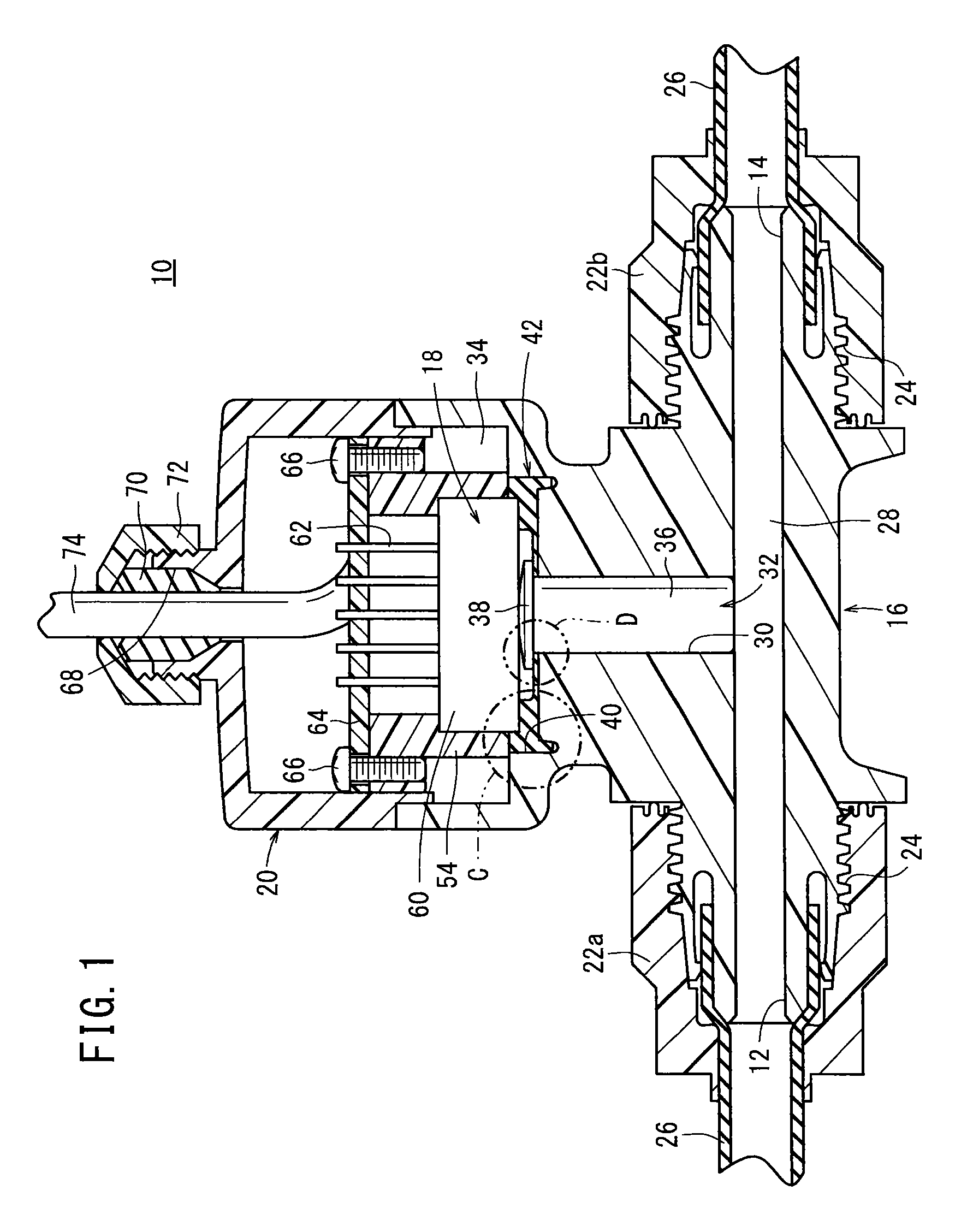
[0041]The pressure detector 10 according to the present invention basically is constructed as described above. Next, operations and advantages of the pressure detector 10 shall be explained.

[0042]First, in an initial state in which pressure fluid is not flowing through the flow passage 28 of the body 16, since a pressing force from the pressure fluid is not imposed on the lower end of the rod-shaped member 32, the rod-shaped member 32 is not pressed and displaced toward the side of the pressure sensor 18, and the pressure sensor 18 is in a condition of not being pressed by the head 38. Thus, no pressure is detected by the pressure sensor 18.

[0043]Next, when a pressure fluid is supplied to the first port 12 on the upstream side, and the pressure fluid passes through the flow passage 28 and flows to the second port 14, as a result of the pressure of the pressure fluid inside the flow passage 28, the lower end of the rod-shaped member 32 is pressed upwardly, and the rod-shaped member 3...

second embodiment

[0062]In the foregoing manner, with the pressure detector 100 the rod-shaped member 104 of the pressure transmitting body 102 is pressed by the pressure of the pressure fluid that flows through the flow passage 28 of the body 16, whereby the sensor element 60 of the pressure sensor 18 is pressed by the upper end part of the rod-shaped member 104, and the pressure of the pressure fluid is detected. Owing thereto, by inserting the rod-shaped member 104 of the pressure transmitting body 102 in the through hole 30 of the body 16, creation of a dead space in the through hole 30 can be avoided. As a result, pooling of liquid or the occurrence of bacteria or generation of bubbles, which would tend to be problematic if such a dead space were created, can reliably be prevented, and the pressure of the pressure fluid can be detected with high accuracy.

[0063]Further, by using the pressure transmitting body 102 in which the rod-shaped member 104 and the seal member 106 are formed together inte...

third embodiment

[0071]In the foregoing manner, with the pressure detector 120 the rod-shaped member 32 is pressed by the pressure of the pressure fluid that flows through the flow passage 28 of the body 16, whereby the sensor element 60 of the pressure sensor 18 is pressed via the skirt section 124 of the seal member 122, which is abutted by the upper end of the rod-shaped member 32, and then the pressure of the pressure fluid is detected. Owing thereto, by insertion of the rod-shaped member 32 in the through hole 30 of the body 16, creation of a dead space in the through hole 30 can be avoided. As a result, pooling of liquid or the occurrence of bacteria or generation of bubbles, which would tend to be problematic if a dead space were created, can reliably be prevented, and the pressure of the pressure fluid can be detected with high accuracy.

[0072]Further, since the rod-shaped member 32 and the seal member 122 can be formed separately from different materials, ease of assembly of the pressure de...


PUM

PropertyMeasurementUnit
angleaaaaaaaaaa
pressureaaaaaaaaaa
outer diameteraaaaaaaaaa

Abstract

The present invention relates to a pressure detector. In a body that constitutes part of the pressure detector, a through hole is formed, which is directed upwardly from a substantially central portion of a flow passage through which a pressure fluid flows. The through hole communicates with a sensor chamber in which a pressure sensor is disposed, and a rod-shaped member is disposed displaceably in the through hole. In addition, an end of the rod-shaped member, which is exposed to the flow passage, is pressed by the pressure fluid and displaced upwardly thereby, and pressure is detected as a result of the pressure sensor being pressed by a head of the rod-shaped member.

Description

CROSS-REFERENCE TO RELATED APPLICATION[0001]This application is based upon and claims the benefit of priority from Japanese Patent Application No. 2012-025755 filed on Feb. 9, 2012, the contents of which are incorporated herein by reference.BACKGROUND OF THE INVENTION[0002]1. Field of the Invention[0003]The present invention relates to a pressure detector for detecting the pressure of a fluid that flows through the interior of a flow passage.[0004]2. Description of the Related Art[0005]Heretofore, for example, in a manufacturing process for semiconductor manufacturing or the like, liquids consisting of chemicals and pure water or the like are used, and a pressure detector is connected with respect to tubes through which such liquids are made to flow, whereby measurement of the pressure of the liquid that flows through the interior of the tubes is carried out by the pressure detector.[0006]As one type of such a pressure detector, for example, as disclosed in Japanese Laid-Open Patent...

Claims


Application Information

Patent Timeline
Patent Type & Authority Patents(United States)
IPC IPC(8): G01L7/08G01L19/00G01L19/06G01L13/02
CPCG01L7/08G01L19/0023G01L19/0038G01L19/0645G01L19/00G01L19/06
Inventor FUKANO, YOSHIHIROUCHINO, TADASHI
Owner SMC CORP
Why Eureka
Try Eureka