Filter device

a filter device and filter technology, applied in the direction of filter cartridges, filter feed/discharge, filter elements, etc., can solve the problems of cost reduction and acceptable energy cost operation, and achieve the effect of improving filter operation

Inactive Publication Date: 2010-03-23
HYDAC PROCESS TECH
View PDF12 Cites 3 Cited by
  • Summary
  • Abstract
  • Description
  • Claims
  • Application Information

AI Technical Summary

Benefits of technology

[0005]Objects of the present invention are to provide filter devices with improved filter operation from the viewpoint of energy consumption.

Problems solved by technology

This arrangement results in filtration operation with acceptable energy costs and in cost reduction.

Method used


Image

  • Filter device
  • Filter device

Examples


Embodiment Construction

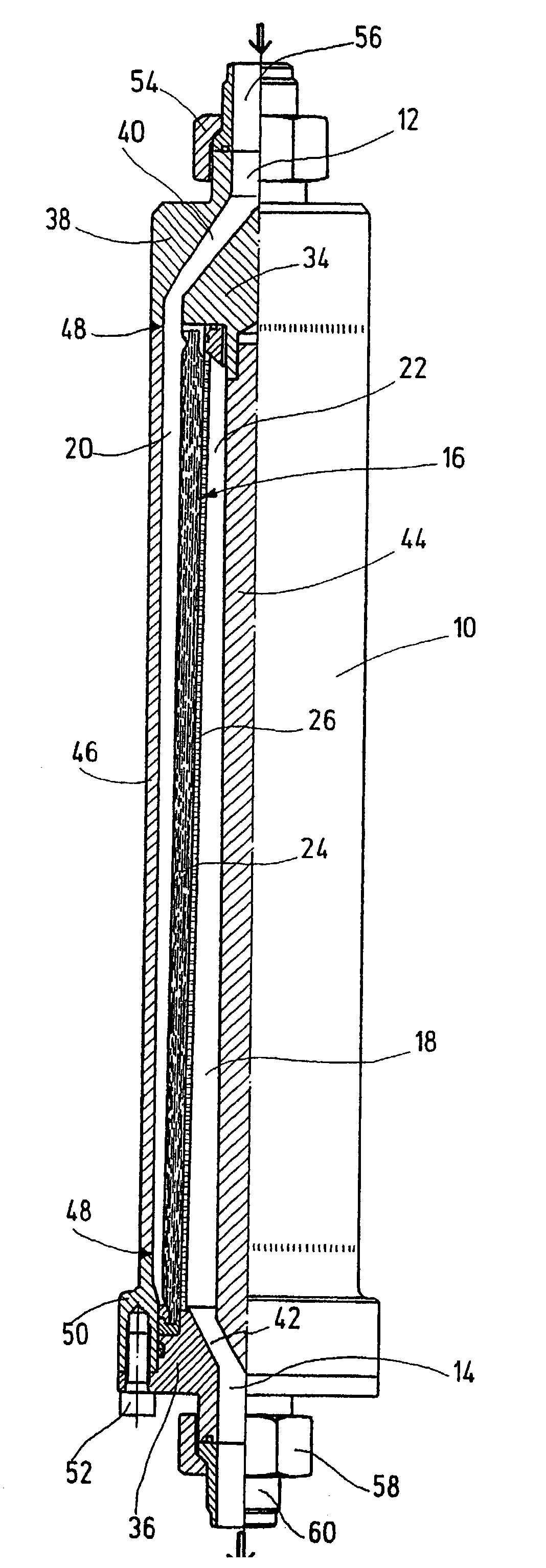
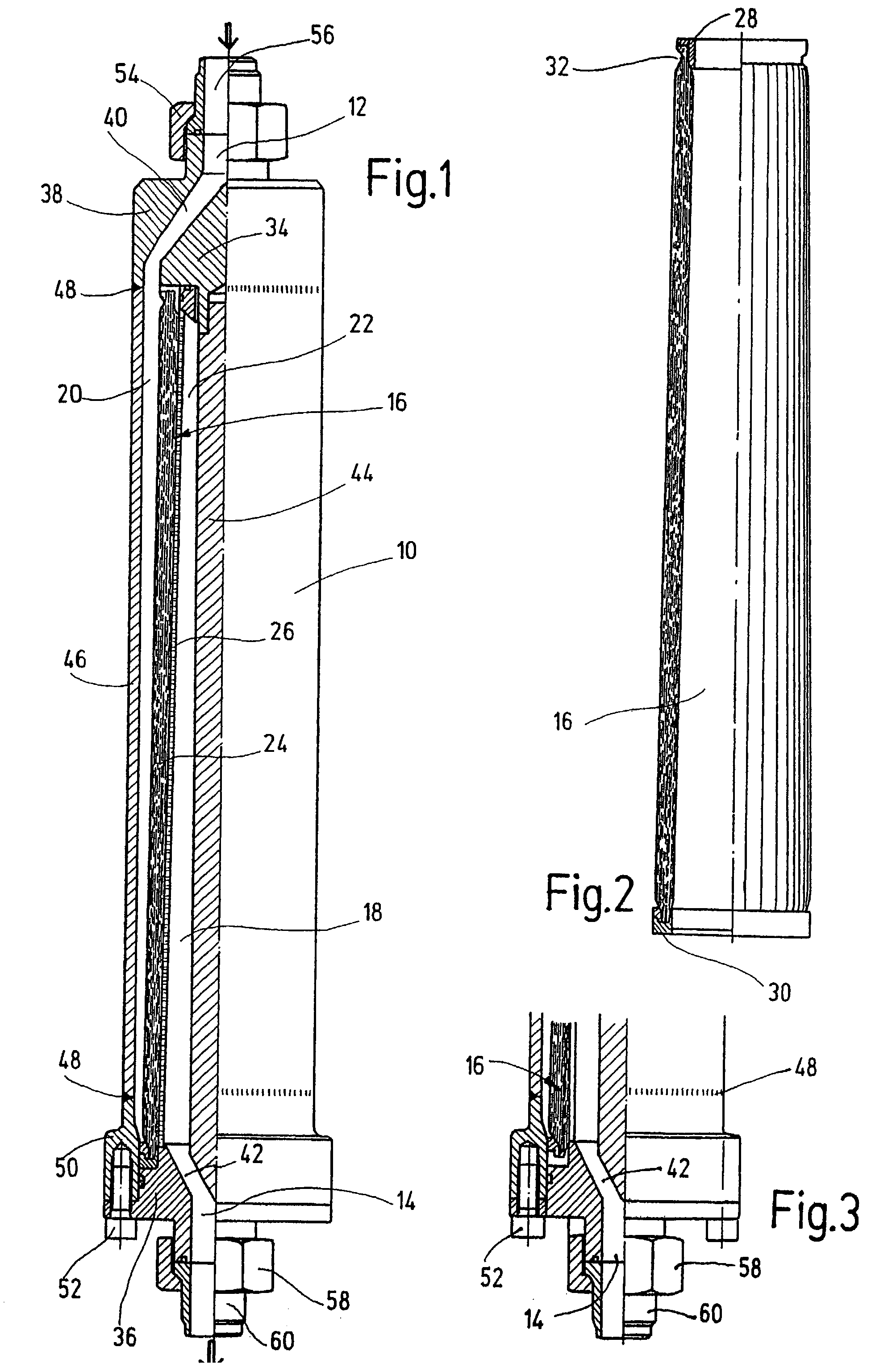
[0014]The filter device, essentially cylindrical as a whole, has a filter housing 10 and filter inlet 12 and filter outlet 14. A filter element 16 as a whole is mounted inside the filter housing 10. This element subdivides a filter space 18 into a first subspace 20 and a second subspace 22. The first subspace 20 tapers, as is shown in FIG. 1 in particular, from the filter inlet 12 to the filter outlet 14 in free cross-section. The second subspace 22 on the other hand, widens from the filter inlet 12 to the filter outlet 14 in cross-section. The tapering of one subspace 20 in cross-section proceeds to the same extent and steadily as does widening of the other subspace 22 in cross-section. Hence, the two subspaces 20 and 22 are juxtaposed so as to be conical in form. In addition, the subspaces 20 and 22 form closed ring-shaped chamber structures inside the filter device.

[0015]The filter element 16, which itself is conical in shape and tapers conically from filter outlet 14 to filter i...


PUM

PropertyMeasurementUnit
flow rateaaaaaaaaaa
areaaaaaaaaaaa
lengthaaaaaaaaaa

Abstract

A filter device includes a filter housing (10), a filter inlet (12), a filter outlet (14), and a filter element (16). The filter element divides a filter area (18) into two partial areas (20, 22). One partial filter areas is conical in form with the cross-section of that partial area (20) being tapered from the filter inlet (12) to the filter outlet (14). The partial areas are separated from each other by the filter element. This arrangement results in an optimum residence time distribution inside the filter device at a uniform flow rate, which is particularly useful for highly viscous fluids such as polymer melts or similar.

Description

FIELD OF THE INVENTION[0001]The present invention relates to a filter device with a filter housing having an inlet, an outlet and a conical filter element subdividing the filter space into two subspaces.BACKGROUND OF THE INVENTION[0002]Filter devices, such as those disclosed in U.S. Pat. Nos. 4,964,984, 4,169,795, 4,052,315, 4,043,918, and in GB 2 075 364), are readily obtainable on the market in a multiplicity of embodiments. The structure of the filter elements, which filter impurities out of a fluid, is determined by the manufacturer. Filter elements of higher quality have a multilayer meshed structure which may rest at least on one supporting fabric to enable the structure to resist higher pressure or pressure peaks.[0003]In principle, it is desirable to arrive at uniform flow behavior inside the filter space during the filtration process, while avoiding dead spaces. The requirements set for the desired behavior increase as the viscosity of the fluid increases, especially if liq...

Claims


Application Information

Patent Timeline
Patent Type & Authority Patents(United States)
IPC IPC(8): B01D29/15B01D29/11B01D29/13B01D29/92B01D39/20
CPCB01D29/15B01D29/925B01D29/96B01D2201/02B01D2201/44
Inventor LANG, NORBERTHAUSDORF, JURGENWNUK, RALF
Owner HYDAC PROCESS TECH
Why Eureka
Try Eureka