
Externally supported foil with reversible camber and variable chord length

a camber and external support technology, applied in vessel construction, renewable energy generation, greenhouse gas reduction, etc., can solve the problems of affecting the production, cost, reliability, maintenance, and production of foils, and developing an actuating mechanism within the confines of an efficient airfoil shape, and still providing structural strength and rigidity

Inactive Publication Date: 2015-11-03
BAILEY STEPHEN LEE
View PDF29 Cites 2 Cited by
  • Summary
  • Abstract
  • Description
  • Claims
  • Application Information

AI Technical Summary

Benefits of technology

The patent describes an improved design for a thin foil that can generate equal amounts of lift when exposed to fluid flow from opposite angles. The foil is supported by an external structure, which helps shape it and reduces drag. This external structure can be designed to improve foil efficiency without needing an active actuation mechanism. The foil itself is designed to deform passively when exposed to fluid flow.

Problems solved by technology

Both approaches typically suffer from the complexity of active mechanisms operating under high loads; thereby, negatively impacting the producibility, cost, reliability, and maintenance of the foil.
Developing an actuating mechanism within the confines of an efficient airfoil shape, while still providing the structural strength and rigidity, becomes problematic.
Increasing the thickness of the foil to accommodate the mechanism results in lower lift and higher drag, ie. poor foil efficiency.
Reducing the foil thickness while accommodating the mechanism leaves little space for structure, ie. poor robustness and structural reliability for the foil.

Method used


Image

  • Externally supported foil with reversible camber and variable chord length
  • Externally supported foil with reversible camber and variable chord length

Examples


Embodiment Construction

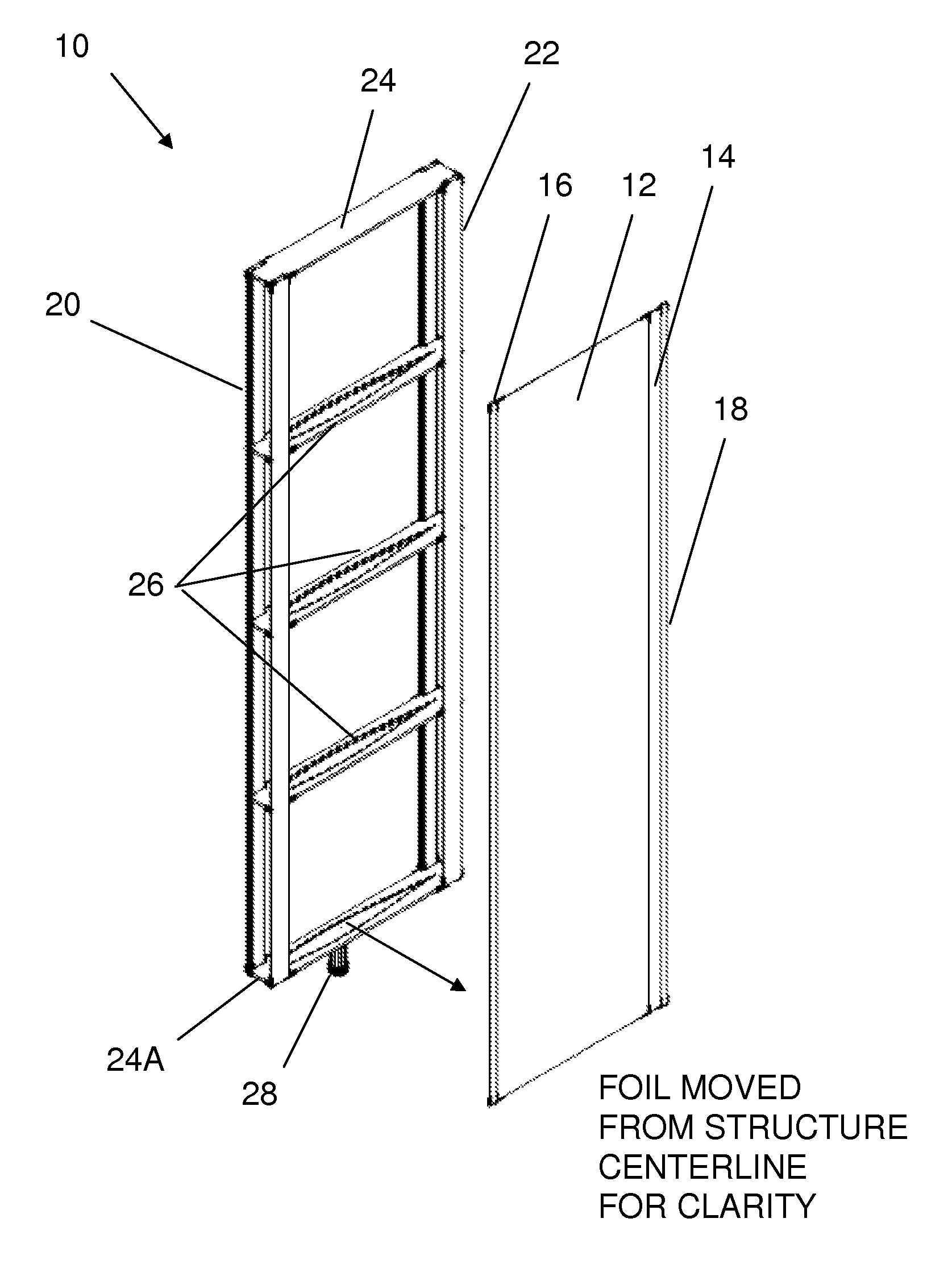
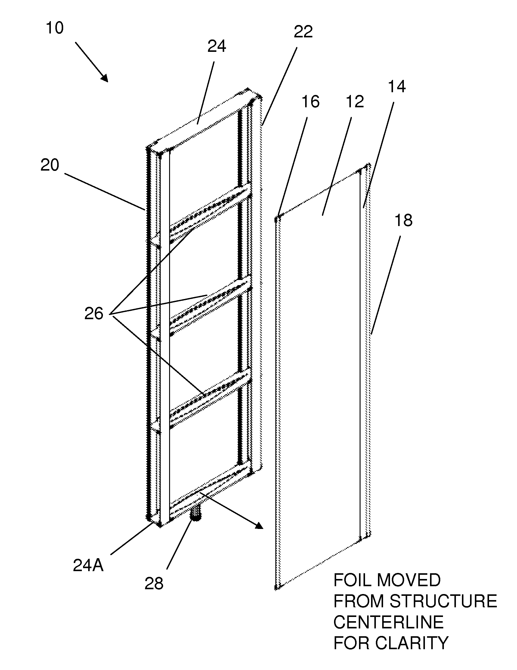
[0011]An externally supported foil with reversible camber and variable chord length 10 is described that allows a thin foil 12 when deformed to an efficient shape to generate lift equally on opposite angles of attack to a fluid flow. The foil 12 is a flat, thin plate that may be semi-rigid or rigid in-plane, but is flexible out of plane along its span. The foil 12 is supported by a pivoting hinge supported leading edge 16 and trailing edge support 18 tensioned between the endcaps 24 and 24A or intermittently supported at the ribs 26 of the external supporting structure. The external structure consists of spars 20 and 22 of shape to minimize parasitic drag connected by open ribs 26 and the endcaps 24 and 24A. The endplates 24 and 24A also function as both wing endplates and the structural attachment to the aircraft, watercraft, or other body. Ribs 26 connect between the spars with an open cutout area provided for the foil 12 and membrane band 14. The perimeter of the cutout forms the...


PUM


Abstract

An externally supported foil with reversible camber and variable chord length is described that allows a thin foil of efficient deformed shape to generate lift equally on opposite angles of attack to a fluid flow. The foil is supported at the leading and trailing edges to ribs that are in turn connected to spanwise spars forming an external structure attachable to a body. The foil is held by leading edge hinge(s) and trailing edge elastic membrane(s) along the span or at the ribs. Membrane pretension keeps the foil taut while generating no lift when parallel to a flow. When rotated by an external mechanism to generate an angle of attack, the membrane stretches due to the differential pressures generated on the foil surface; thereby, passively increasing the chord length and camber. Rib cutouts dictate the deformed aerodynamic or hydrodynamic foil shape that then generates lift.

Description

CROSS-REFERENCE TO RELATED APPLICATIONS[0001]This application claims the benefit of provisional patent application 61 / 489,620 filed 2011 May 24 by the present inventor.FEDERALLY SPONSORED RESEARCH[0002]None.SEQUENCE LISTING[0003]None.BACKGROUNDPrior Art[0004]The following is a tabulation of some prior art that presently appears relevant:[0005]Pat. No.Issue DatePatentee1,341,758Jun. 1, 1920Parker3,332,383Jul. 25, 1967Wright4,537,143Aug. 27, 1985Gaide5,181,678AJan. 26, 1993Widnall, et al.6,173,925B1Jan. 16, 2001Mueller, et al.6,622,974B1Sep. 23, 2003Dockter, et al.2010 / 0090067A1Apr. 15, 2010Pfaller7,939,178B2May 10, 2011Sar, et al.7,963,485B2Jun. 21, 2011Koneczny8,113,470B1Feb. 14, 2012Motosko[0006]Foils are utilized in a variety of aerodynamic and hydrodynamic applications including aircraft wings, ship and aircraft rudders, and sailboat sails and centerboards. In the former, aircraft main wings typically produce an upward lift. In the latter, rudders, sails, and centerboards require...

Claims


Application Information

Patent Timeline
IPC IPC(8): F03D7/02F15D1/00
CPCF15D1/00F03D7/022F03D7/0236F03D1/0675F03D3/062F05B2240/30Y02E10/74B63H25/38B64C3/48F15D1/10B63H9/0635B63H9/061Y02E10/72Y02T50/10
Inventor BAILEY, STEPHEN LEE
Owner BAILEY STEPHEN LEE
Learn More