Laminated rotor structure for a permanent magnet synchronous machine

a technology of synchronous machines and rotors, which is applied in the direction of dynamo-electric machines, magnetic circuit rotating parts, magnetic circuit shapes/forms/construction, etc., can solve the problems of leakage flux of rotors, and achieve the effect of minimizing leakage flux and preventing excessive heating of magnets

Active Publication Date: 2015-11-03
DANFOSS EDITRON OY
View PDF14 Cites 13 Cited by
  • Summary
  • Abstract
  • Description
  • Claims
  • Application Information

AI Technical Summary

Benefits of technology

[0007]The objective of the invention is to remedy the defects of the prior art referred to above. In particular, the objective of the invention is to disclose a novel laminate rotor structure wherein the excessive heating of the magnets has been prevented and wherein the magnetic fluxes are made to move in an optimal fashion, minimizing the leakage fluxes.SUMMARY OF THE INVENTION
[0010]In one embodiment of the invention, the air channel includes a ferromagnetic neck in the direction of the bisector of the angle between the magnets, i.e. in the radial direction of the rotor, dividing the air channel in two subchannels that are symmetrical relative to the neck. Appropriately dimensioned, the neck minimizes the need for magnetic material and the leakage flux, directing the magnetic flux around the subchannels. Further, the neck acts as a mechanical radial support to the centrifugal forces of the rotor.
[0011]In one embodiment of the invention, the angle between a pair of permanent magnets that opens outward from the rotor includes a non-ferromagnetic support structure extending axially through the rotor. This support structure, combined with the bars of the damper winding that are suitably placed close to the outer perimeter of the rotor, reduces the armature reaction of the generator, which leads to better properties for the machine.
[0013]In one embodiment of the invention, the support structure includes two non-ferromagnetic support bolts disposed at a distance from each other in the radial direction of the rotor, and an air gap disposed in the radial direction of the rotor to connect them. Thus, the support bolts together with the more narrow air gap therebetween constitute a radial wall that directs the magnetic flux to pass between the magnets mainly in the radial direction. Further, the support bolts give mechanical strength to the laminate body of the rotor in order better to resist centrifugal forces.
[0014]The laminated rotor structure for a permanent magnet synchronous machine according to the invention provides considerable advantages as compared to the prior art. The temperature of the rotor and, most importantly, of the magnets therein can be kept within allowable limits to maintain their magnetic properties. Further, the magnetic flux is made to move in the rotor structure in an optimal fashion by virtue of the properly placed flux blocks, minimizing leakage fluxes of the permanent magnets, which has a considerable effect on the size of the electric machine. In addition, the rotor is made mechanically robust by virtue of the inventive structure.

Problems solved by technology

The ferromagnetic disk pack constitutes a good body for the rotor around the magnets, but heating of the rotor and particularly of the magnets causes problems specifically in large machines.
Another problem is the leakage flux of the rotor and the armature reaction, i.e. the magnetic flux tends to move sideways on the rotor pole, which is not a desirable phenomenon.

Method used


Image

  • Laminated rotor structure for a permanent magnet synchronous machine
  • Laminated rotor structure for a permanent magnet synchronous machine
  • Laminated rotor structure for a permanent magnet synchronous machine

Examples


Embodiment Construction

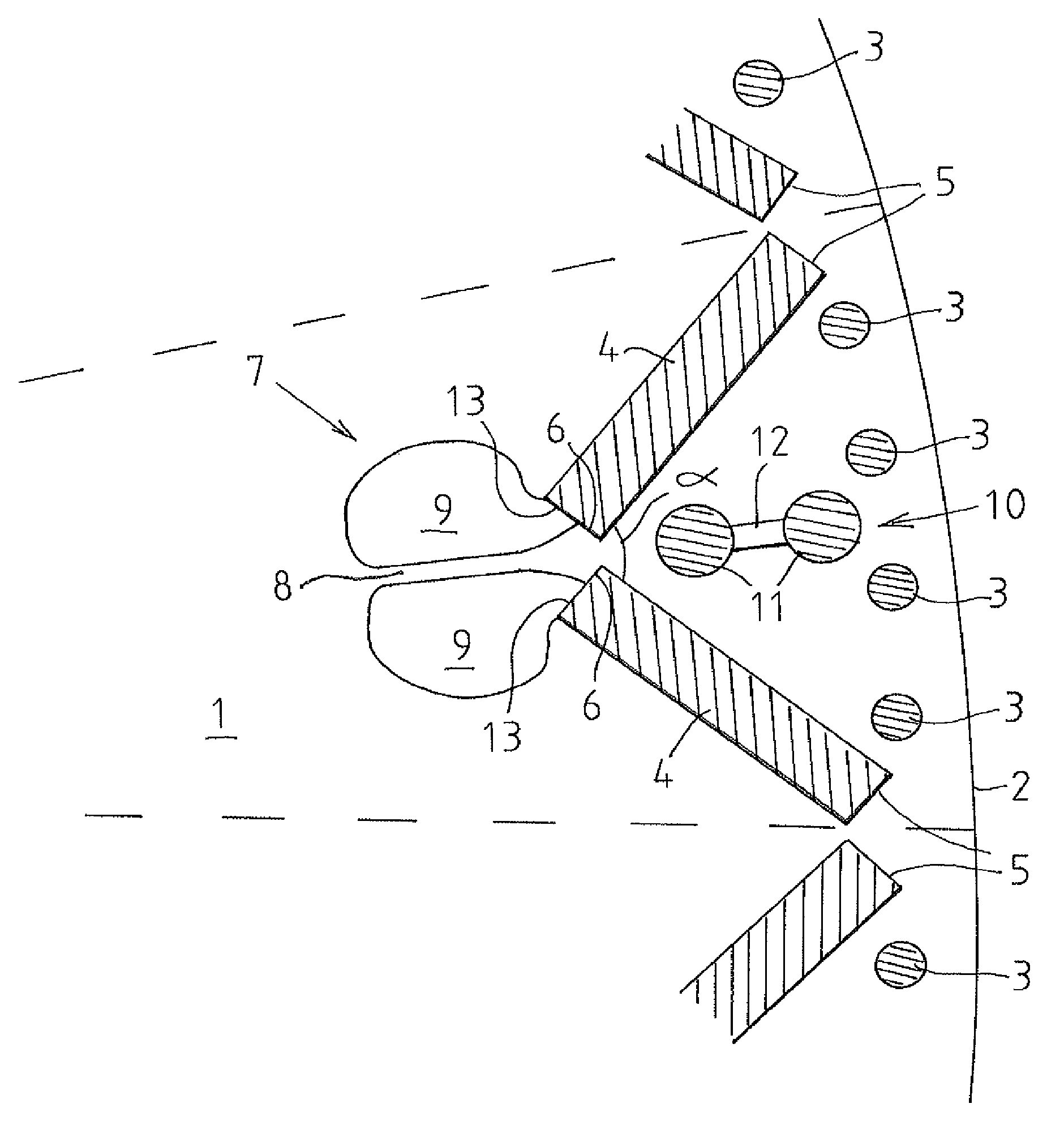
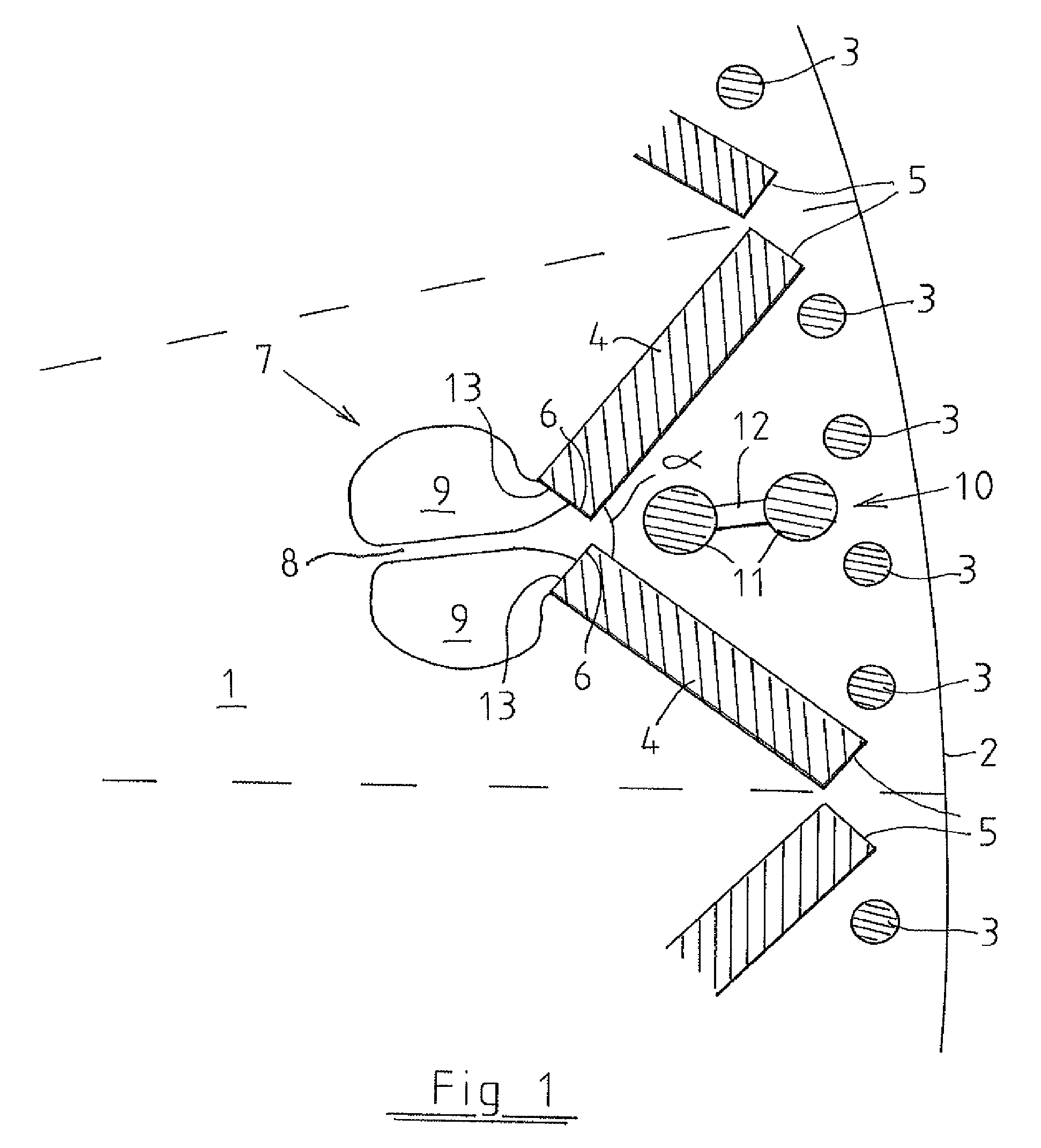
[0018]FIG. 1 presents the structure of a rotor that has been laminated from ferromagnetic disks in a permanent magnet synchronous machine. More specifically, a sectional view of a sector delimited by dash lines, including one V-shaped pair of permanent magnets. There may be a number of these kinds of sectors present in the rotor, for example at least eight or even much more.

[0019]The rotor thus consists of a large number of ferromagnetic round disks tightly disposed side by side as a single pack in the axial direction of the rotor. The structures included in the sector extend axially, identically and unchangeably, through the entire disk pack structure of the rotor. In proximity to the surface 2 of a disk 1 inside the rotor there are a number of generally copper-made bars 3 of a damper winding, connected in a manner known per se to copper short-circuiting rings disposed at each end of the rotor. Two permanent magnets 4 are disposed at an angle α to each other so that the first ends ...


PUM


Abstract

The invention relates to a laminated rotor structure for a permanent magnet synchronous machine wherein disks (1) of a ferromagnetic material constitute the body of the rotor. The body includes bars (3) of a damper winding that extend axially close to the surface (2) from one end thereof to the other, and a circle of permanent magnets (4) disposed in a V-shaped configuration inside the circle formed by the bars, in which permanent magnets the first ends (5) are disposed close to the outer perimeter of the rotor and the second ends (6) are disposed closer to the central axis of the rotor. According to the invention, two permanent magnets (4) constitute a pair of permanent magnets wherein the magnets are disposed at an angle (a) to each other so that their first ends (5) are disposed at a distance from each other and their second ends (6) in proximity to each other. In addition, a pair of permanent magnets includes an air channel (7) that extends axially through the laminar structure of the rotor in direct heat transfer contact with the second ends (6) of the magnets in the pair of magnets.

Description

[0001]This application is a National Stage Application of PCT / FI2012 / 050065, filed 25 Jan. 2012, which claims benefit of Serial No. 20115076, filed 26 Jan. 2011 in Finland and which applications are incorporated herein by reference. To the extent appropriate, a claim of priority is made to each of the above disclosed applications.FIELD OF THE INVENTION[0002]The invention relates to a laminated rotor structure for a permanent magnet synchronous machine as defined in the preamble of claim 1.BACKGROUND OF THE INVENTION[0003]In permanent magnet synchronous machines it is common to use laminated rotor structures, i.e. disk rotors, wherein the actual body of the rotor around the shaft is made from a large number of round and thin ferromagnetic metal disks that are identical in shape, disposed perpendicularly relative to the shaft and packed into a tight assembly. The permanent magnets are then provided to the body of the rotor, either to the surface or embedded deeper as rods extending fr...

Claims


Application Information

Patent Timeline
Patent Type & Authority Patents(United States)
IPC IPC(8): H02K1/32H02K9/06H02K1/27H02K1/22H02K9/02
CPCH02K9/06H02K1/223H02K1/2766H02K1/32H02K9/02
Inventor PARVIAINEN, ASKO
Owner DANFOSS EDITRON OY
Why Eureka
Try Eureka