Disk brake

a technology of disc brakes and calipers, which is applied in the direction of fluid actuated brakes, braking systems, transportation and packaging, etc., can solve the problems of high possibility of occurrence of brake judder phenomenon, pin insertion holes of pins of respective arm portions that interfere with the inner wall surfaces of sliding pins, etc., and achieve the effect of ensuring the sliding ability of the caliper

Active Publication Date: 2015-11-10
HITACHI ASTEMO LTD
View PDF13 Cites 11 Cited by
  • Summary
  • Abstract
  • Description
  • Claims
  • Application Information

AI Technical Summary

Benefits of technology

[0004]An object of the present invention is to provide a disk brake capable of ensuring slidability of a caliper relative to a mount member.

Problems solved by technology

However, according to the disk brake disclosed in Japanese Patent Public Disclosure No. 2006-207722, when the mount member receives a braking torque from the pair of frictional pads, especially due to elastic deformation of an outer-side leg portion of the mount member, the slide pins may interfere with the inner wall surfaces of the pin insertion holes of the respective arm portions.
More specifically, the slide pins scrape interiors of the pin insertion holes, thereby increasing sliding resistance between the slide pins and the inner walls of the pin insertion holes during a braking operation, leading to a high possibility of occurrence of a brake judder phenomenon.

Method used


Image

  • Disk brake
  • Disk brake
  • Disk brake

Examples


first embodiment

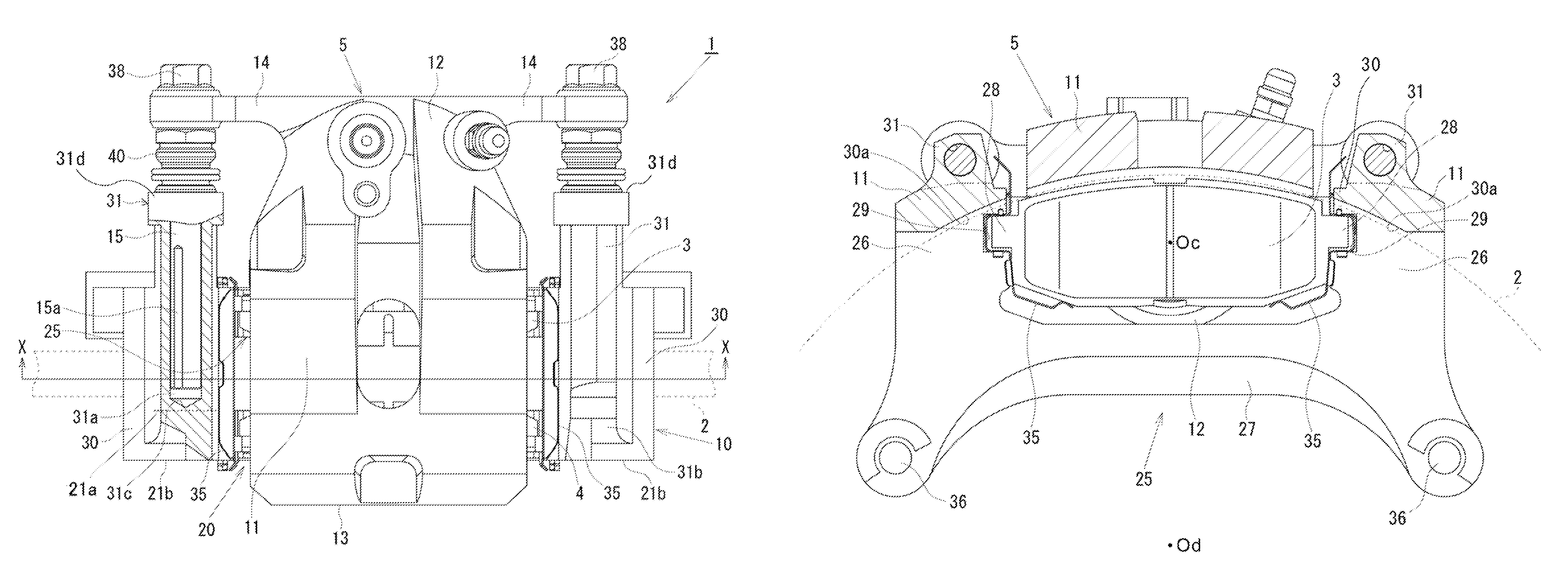
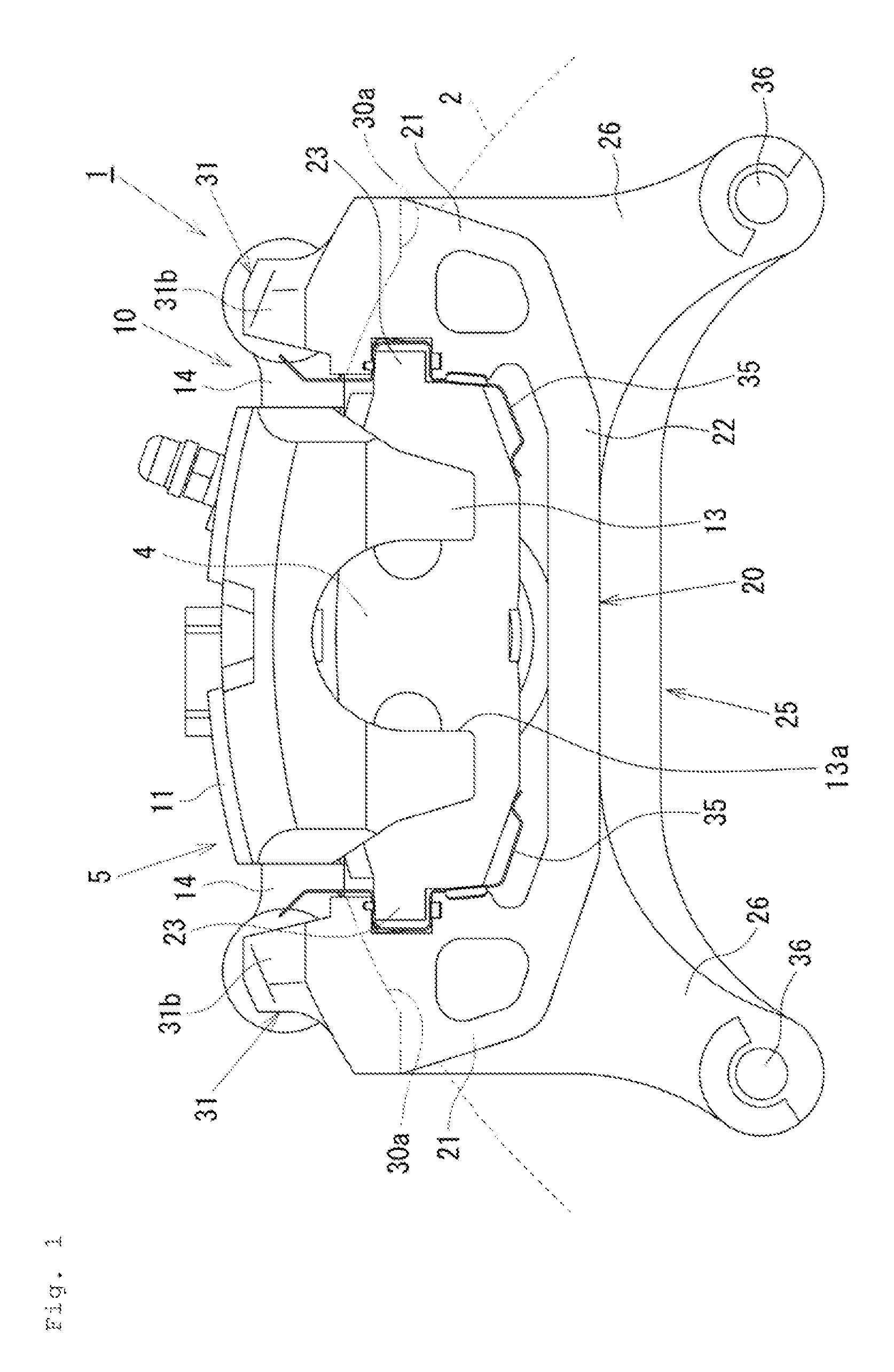
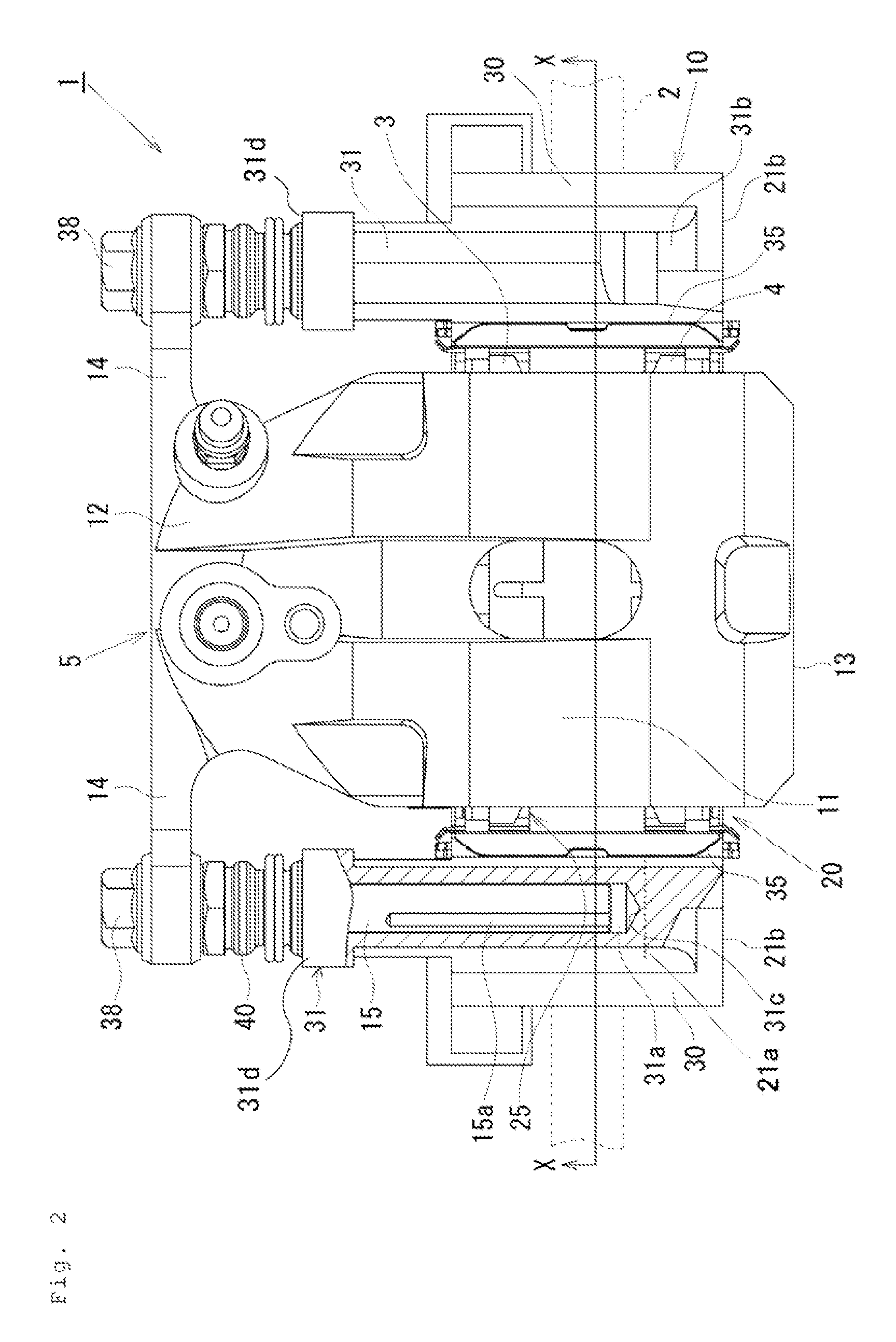
[0015]Hereinafter, a first embodiment will be described with reference to FIGS. 1 to 5. In the following description, the term “outer side” will be used to refer to a wheel side as viewed at a disk rotor 2 (the right side in FIG. 2), and the term “inner side” will be used to refer to a central side as viewed at the disk rotor 2 in a lateral direction of a vehicle, which is an opposite side from the wheel (the left side in FIG. 2). Further, the term “disk axial direction” will be used to refer to an axial direction of a rotational axis of the disk rotor 2. The term “disk radial direction” will be used to refer to a radial direction of the disk rotor 2. The term “disk rotational direction” will be used to refer to a rotational direction of the disk rotor 2.

[0016]As illustrated in FIGS. 1 to 4, a disk brake 1 according to the first embodiment includes a pair of frictional pads, i.e., an inner-side frictional pad 3 and an outer-side frictional pad 4 disposed at opposite sides of the dis...

second embodiment

[0047]In the disk brake the caliper 105 includes the bottomed cylindrical cylinder portion 12 and the driving unit 51, 52, 53. The cylinder portion reciprocally movably contains the piston configured to press the frictional pads 3 and 4, and further contains the piston thrust mechanism configured to mechanically thrust the piston. The driving unit 51, 52, 53 is fixed to the bottom side of the cylinder portion 12 so as to provide a thrust force to the piston thrust mechanism. The driving unit 51, 52, 53 is disposed so as to extend from the center of the cylinder portion along the disk rotational direction. When the caliper 105 provided with this driving unit 51, 52, 53 is attached to the mount member 10, even through the center of gravity of the caliper 105 is positioned at the bottom side of the cylinder portion 12 due to the driving unit 51, 52, 53, it is possible to ensure the slidability of the caliper 105.

[0048]In the disk brake according to the second embodiment, the pin inser...


PUM


Abstract

A disk brake including a mount member having a pin insertion portion integrally connected to a connection portion so as to outwardly protrude from an outer surface of the connection portion in a radial direction of a disk rotor. A tip of a pin insertion hole of the pin insertion portion is positioned at an inner side of a vehicle relative to an outer portion. Thus, it is possible to prevent a braking torque from affecting the pin insertion portion of the mount member. As a result, it is possible to prevent a slide pin from interfering with an inner wall surface of the pin insertion hole, thereby preventing a brake judder phenomenon from occurring during a braking operation.

Description

BACKGROUND OF THE INVENTION[0001]The present invention relates to a disk brake for use in braking of a vehicle.[0002]Conventional disk brakes include a mount member attached to a non-rotatable portion of a vehicle, and a caliper, as disclosed in Japanese Patent Public Disclosure No. 2006-207722. The mount member includes a pair of arm portions, and the pair of arm portions are spaced apart from each other along a circumferential direction of a disk and are disposed so as to axially extend over the disk. The caliper is slidably attached to the arm portions of the mount member with use of, for example, slide pins. An inner-side frictional pad and an outer-side friction pad are pressed against the respective surfaces of the disk by the caliper. The slide pins are attached to the caliper, and are slidably fitted in pin insertion holes formed at the respective arm portions of the mount member.[0003]However, according to the disk brake disclosed in Japanese Patent Public Disclosure No. 20...

Claims


Application Information

Patent Timeline
Patent Type & Authority Patents(United States)
IPC IPC(8): F16D55/22B60T1/06F16D55/2265F16D55/227F16D55/00F16D121/04F16D121/24F16D123/00F16D125/36F16D125/48F16D125/50
CPCB60T1/065F16D55/227F16D55/22655F16D2055/0008F16D2121/04F16D2121/24F16D2123/00F16D2125/36F16D2125/48F16D2125/50F16D65/092F16D65/095F16D65/14
Inventor SUZUKI, SHINJIWATANABE, JUNTSURUMI, SATORU
Owner HITACHI ASTEMO LTD
Why Eureka
Try Eureka