Eureka AIR delivers breakthrough ideas for toughest innovation challenges, trusted by R&D personnel around the world.

Video wall mount having adjusting structure

a technology of video wall mount and adjustment structure, which is applied in the direction of picture frames, identification means, instruments, etc., can solve the problems of inability to adjust the structure, the tolerance of the wall mount is practically inevitable, and the gap between the wall mount and the frame is large, so as to achieve the effect of simple structure, reduced cost and simple operation

Inactive Publication Date: 2015-11-10
AOPEN
View PDF9 Cites 20 Cited by
  • Summary
  • Abstract
  • Description
  • Claims
  • Application Information

AI Technical Summary

Benefits of technology

The patent text is describing a way to adjust the vertical gap between display screens using a mounting hook and two adjusting bolts. The goal is achieved by rotating the second adjusting bolt to abut the locking portion, which causes the load-bearing piece of the mounting hook to move upward or downward, ultimately rising or displacing the television. The adjusting structure is simple and only requires a small number of elements, reducing costs in manufacturing. The adjusting operation is intuitive and can be performed immediately without additional reading of instructions or experiments.

Problems solved by technology

For a product of a video wall, problems in aspects of tolerance, gaps, and evenness is practically inevitable regardless of how precise construction is carried out.
Existing adjusting manners include a manner of adding a pad that is used to adjust a gap or evenness, an automatic adjusting structure using a hydraulic apparatus and the like, and also a manual adjusting structure using a complex frame structure or a multiple linkage manner; however, all these adjusting structures need multiple elements, so that the structure is very complex.
Moreover, in the use of an automatic adjusting structure, a frame structure or a multi-linkage structure, because a large number of elements are used, the manufacturing procedure is complex and the cost is also very high.
Moreover, for both an automatic adjusting structure and a multi-linkage adjusting structure, the adjusting manners need to be learned first to perform needed adjustment accurately, which is relatively inconvenient for a user.

Method used


Image

  • Video wall mount having adjusting structure
  • Video wall mount having adjusting structure
  • Video wall mount having adjusting structure

Examples


Embodiment Construction

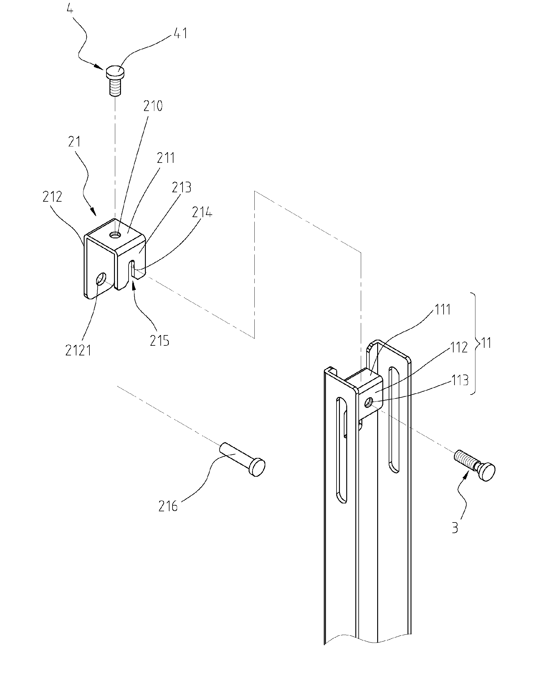
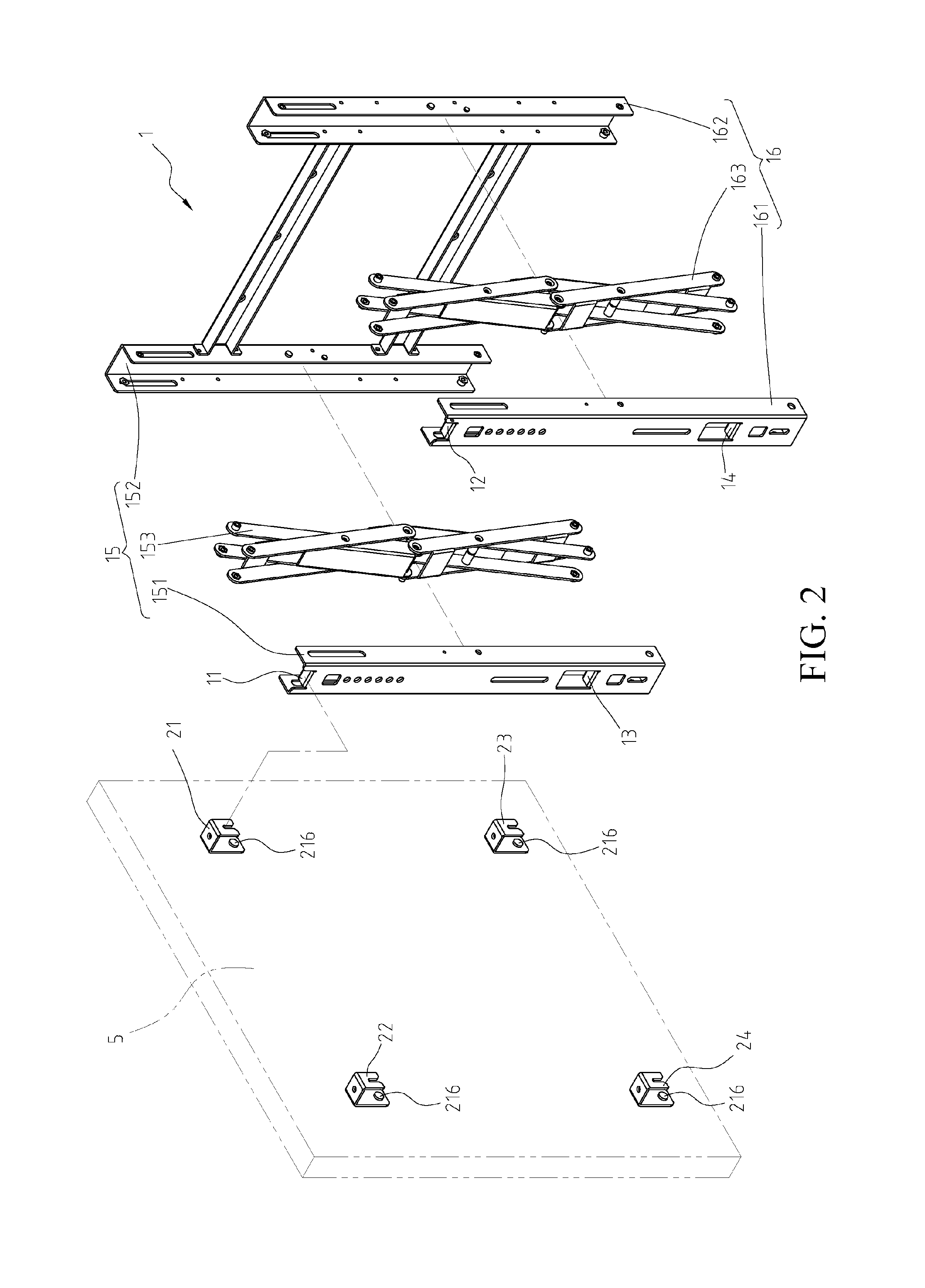
[0019]In FIG. 2 to FIG. 7: FIG. 2 is a schematic view of a television and a video wall mount according to a first embodiment of the present creation; FIG. 3 is a partial enlarged view of the video wall mount according to this embodiment; FIG. 4 and FIG. 5 are respectively schematic views (1) and (2) of adjustment of front-surface evenness according to this embodiment; and FIG. 6 and FIG. 7 are schematic views of vertical adjustment according to this embodiment.

[0020]Referring to FIG. 2 and FIG. 3 at the same time, the video wall mount in this embodiment includes a wall fixing rack 1, four mounting hooks 21, 22, 23, 24, a first adjusting bolt 3, and a second adjusting bolt 4, so as to adjust a mounting position of a television 5. Herein, although the television 5 is used as an example, instead of specifying a display screen having a television function, a variety of display screens may be adjusted. In this embodiment, the wall fixing rack 1 includes a left support 15 and a right supp...


PUM


Abstract

The present creation is a video wall mount having an adjusting structure, which includes a wall fixing rack, a mounting hook, a first adjusting bolt, and a second adjusting bolt. After the mounting hook is locked to the back of a television, and is assembled to the video wall mount, when front-surface evenness needs adjustment, only the first adjusting bolt needs to be rotated. The second adjusting bolt is rotated to adjust a vertical gap. Because only the mounting hook and two adjusting bolts need to be used to adjust front-surface evenness and a vertical gap, a small number of elements are used, and the structure is very simple. In fabrication, the cost can be significantly decreased. Moreover, such an adjusting manner is intuitive and simple in operations, and adjustment operations can be performed immediately without additional reading of instructions or experiments.

Description

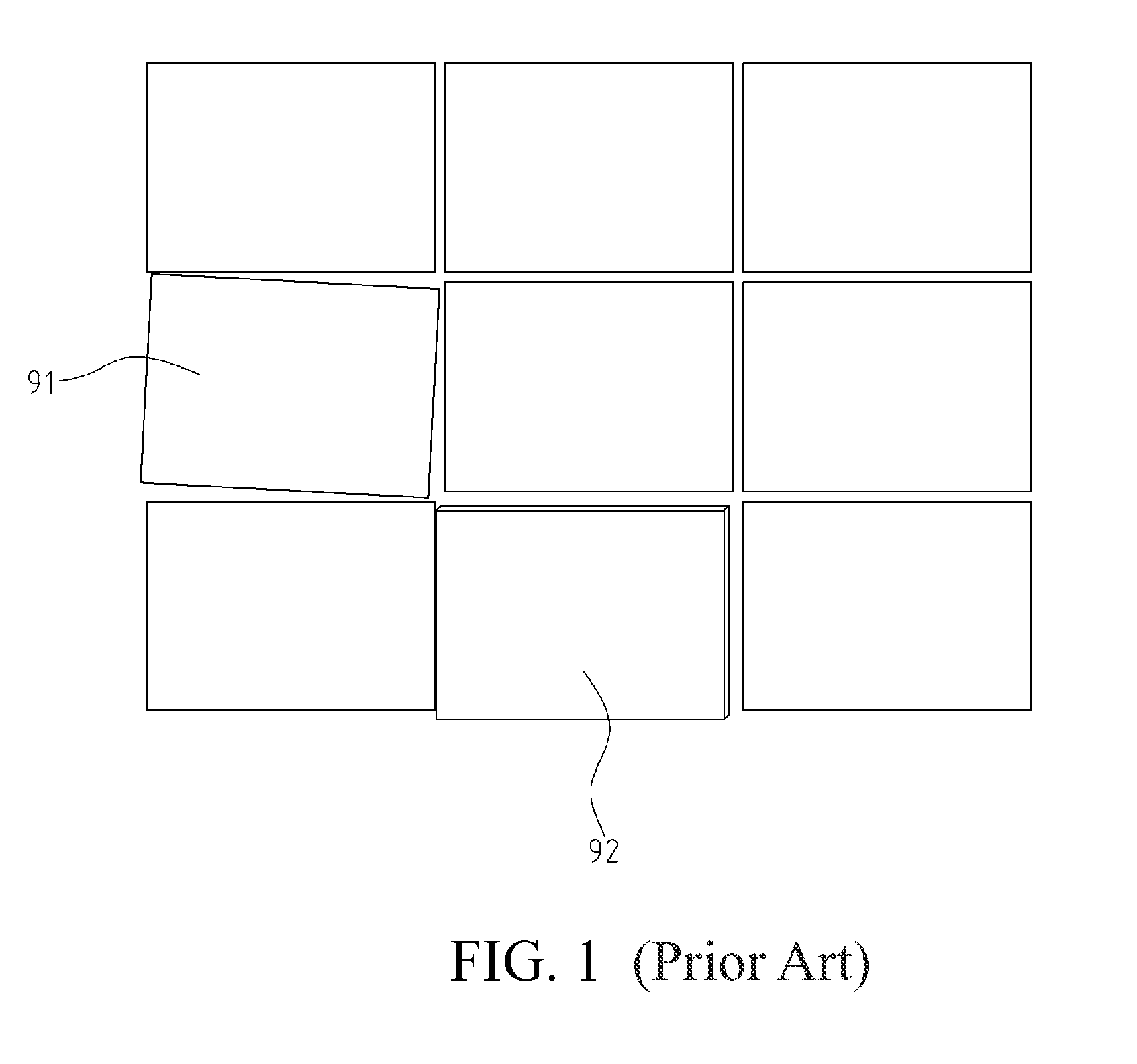
CROSS-REFERENCES TO RELATED APPLICATIONS[0001]This non-provisional application claims priority under 35 U.S.C. §119(a) on Patent Application No. 103221004 filed in Taiwan, R.O.C. on 2014, Nov. 26, the entire contents of which are hereby incorporated by reference.BACKGROUND[0002]1. Technical Field[0003]The present creation relates to a video wall mount, and more particularly to a video wall mount on which a left-right or front-rear position of a television can be adjusted.[0004]2. Related Art[0005]Televisions have increasingly large sizes and become increasingly thinner nowadays. To save mounting space and take overall appearance into consideration, televisions are often mounted onto a wall by using a wall mount. Moreover, because televisions have increasingly lower prices, many sellers also dispose a video wall to present commodities or play advertisements. As shown in FIG. 1, for a video wall assembled by multiple televisions, whether all televisions are tightly connected is very i...

Claims


Application Information

Patent Timeline
IPC IPC(8): A47G1/24A47G1/16F16M13/02F16M11/04
CPCF16M13/022A47G1/24A47G1/1613F16M13/02F16M11/04F16M11/046F16M11/048F16M11/105F16M11/2092F16M2200/061G09F9/3026
Inventor CHENG, SHENG-HSIUNG
Owner AOPEN
Why Eureka
Eureka Blog
Learn More