
Gaming machine

a gaming machine and gaming technology, applied in the field of gaming machines, can solve problems such as heat generation in components, and achieve the effects of reducing the space for installing the gaming machine, preventing a malfunction of components, and reducing the space for gaming machines

Active Publication Date: 2015-11-10
INTERBLOCK DOO
View PDF13 Cites 2 Cited by
  • Summary
  • Abstract
  • Description
  • Claims
  • Application Information

AI Technical Summary

Benefits of technology

The present gaming machine has a specialized vibration system that is built into the armrest of the machine. This system uses a low-pitched sound to provide a tactile experience for the player. This helps to make the game more interesting and engaging for the player. The machine also has a recess portion that allows for air exhaust, preventing malfunctions caused by heat. This design prevents modification to the main portion of the machine and reduces the workload of the operator. Additionally, the recess portion ensures that air can be effectively exhaust from multiple machines arranged in a line. This helps to improve the efficient use of space in game arcades.

Problems solved by technology

When the gaming machines are operating, these components generate heat.
Then, when the temperatures in the cabinets rise, the components may cause malfunction (such as abnormal operation of control programs).

Method used


Image

  • Gaming machine
  • Gaming machine
  • Gaming machine

Examples


first embodiment

[First Embodiment]

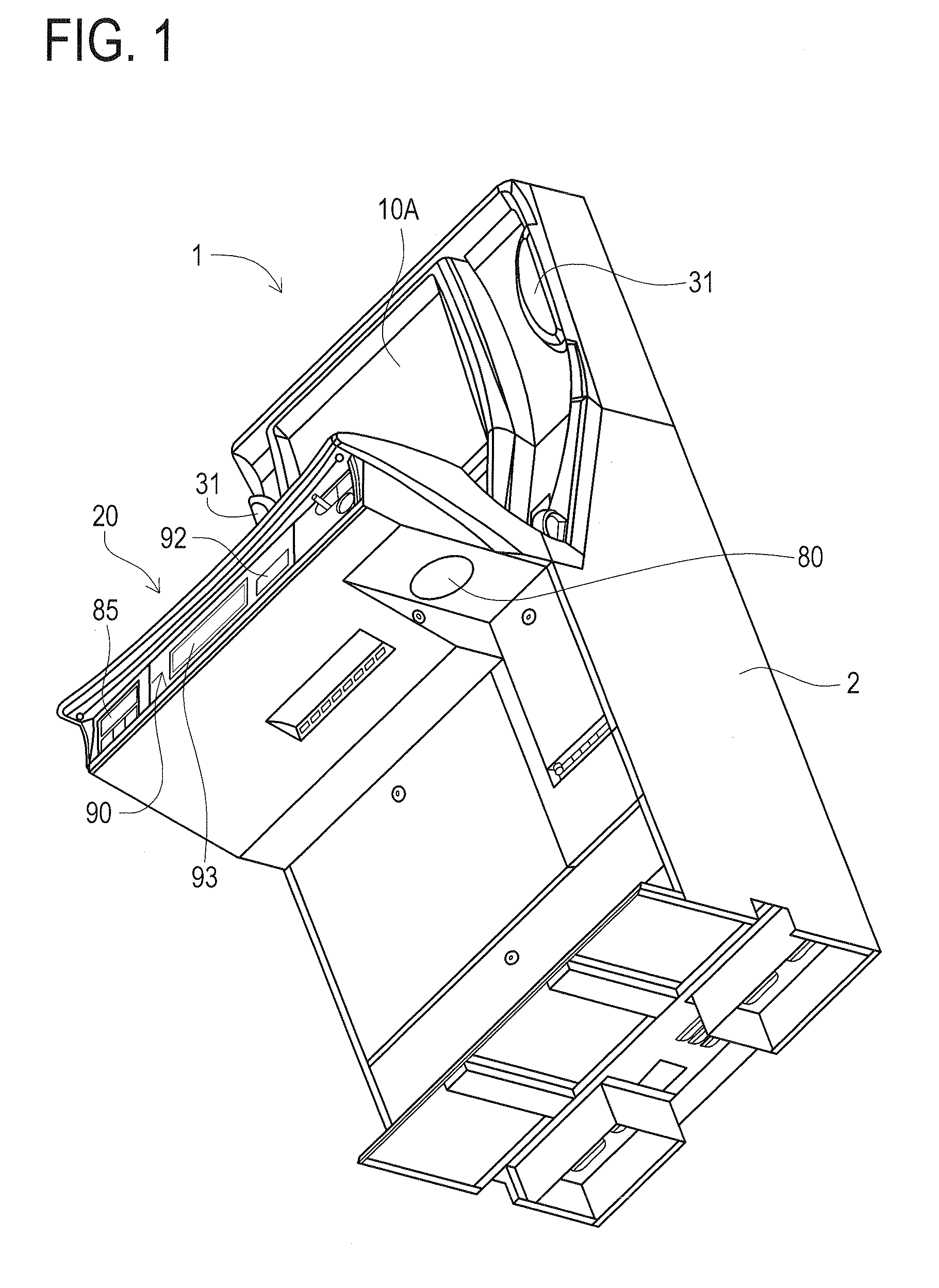
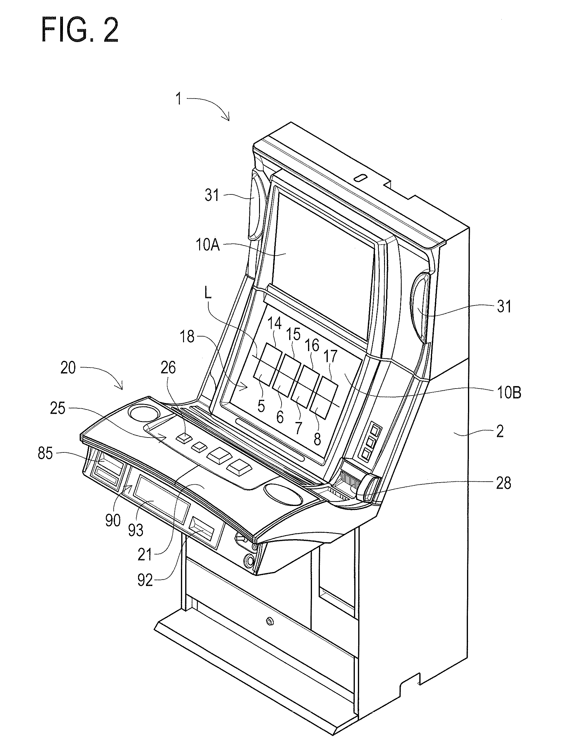
[0035]A gaming machine according to the first embodiment will be described in detail with reference to the drawings as embodied in a slot machine 1.

[0036]The features of the slot machine 1 according to the present invention will be described in detail with reference to the drawings. The slot machine 1 according to the first embodiment is a so-called hybrid-type slot machine. This hybrid-type slot machine has a known transmissive liquid crystal panel arranged in front of a plurality of mechanical reels. The plurality of mechanical reels are rotatably supported. This hybrid-type slot machine turns the transmissive liquid crystal panel into a transparent state when executing a game so as to allow the images of various symbols depicted on the outer peripheral surface of the mechanical reels to be displayed.

[0037]Also, the slot machine 1 is a slanted-type slot machine as is installed in game arcades such as casinos (refer to FIG. 1 and FIG. 2). In a case of the slanted-...

second embodiment

[Second Embodiment]

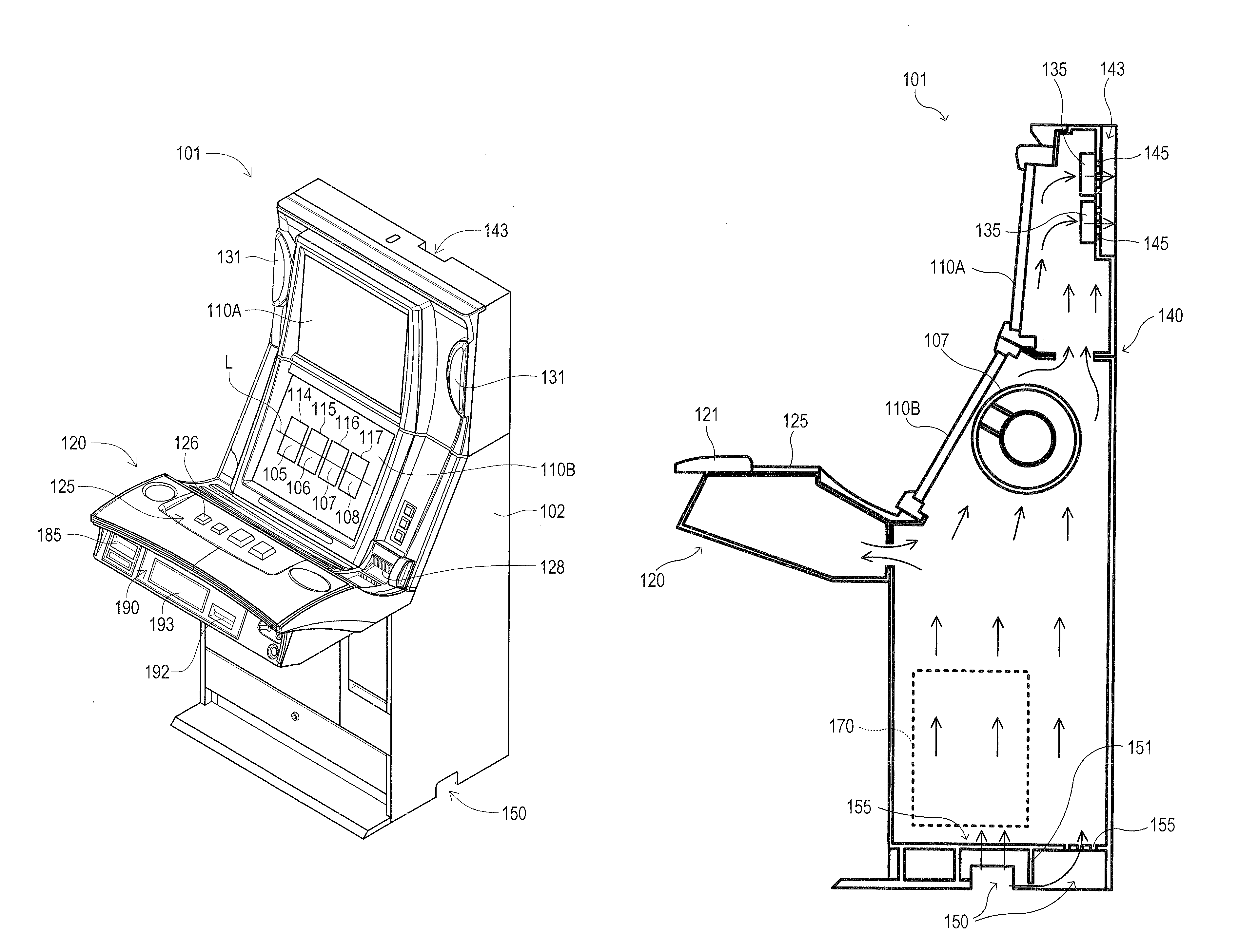
[0092]A gaming machine according to the second embodiment will be described in detail with reference to the drawings as embodied in a slot machine 101.

[0093]The features of the slot machine 101 according to the second embodiment will be described in detail with reference to the drawings. The slot machine 101 according to the second embodiment is a so-called hybrid-type slot machine. This hybrid-type slot machine has a known transmissive liquid crystal panel arranged in front of a plurality of mechanical reels. The plurality of mechanical reels are rotatably supported. This hybrid-type slot machine turns the transmissive liquid crystal panel into a transparent state when executing a game so as to allow the images of various symbols depicted on the outer peripheral surface of the mechanical reels to be displayed.

[0094]Also, the slot machine 101 is a slanted-type slot machine as is installed in game arcades such as casinos (refer to FIG. 6 and FIG. 7). In case of the...


PUM


Abstract

A gaming machine has an armrest for a player to rest his / her arm(s) thereon. The armrest has a woofer specialized in low-pitched sound output inside the armrest. Vibrations produced with the sound output of the woofer are transmitted to the player through the armrest.

Description

CROSS-REFERENCE TO RELATED APPLICATIONS[0001]This application is based upon and claims a priority from the U.S. provisional Patent Application No. 61 / 114,155 filed on Nov. 13, 2008, the U.S. provisional Patent Application No. 61 / 114,149 filed on Nov. 13, 2008, the entire contents thereof are incorporated herein by reference.BACKGROUND[0002]1. Technical Field[0003]One or more aspects of the present invention relate to a gaming machine having a woofer that outputs sounds in a low pitch range.[0004]2. Description of Related Art[0005]Conventionally, various types of gaming machines are installed in game arcades. The various types of gaming machines include a slot machine, a card game machine and so on. These gaming machines stimulate players' interests in games through performing various effects. The various effects include a visual effect based on display on a display device, an auditory effect by sounds output from a speaker and an effect of luminescence by a luminescent device (for i...

Claims


Application Information

Patent Timeline
Patent Type & Authority Patents(United States)
IPC IPC(8): A63F13/90G07F17/32
CPCG07F17/32G07F17/3202G07F17/3216
Inventor ENDO, YOSHIHIDEIZAWA, TAKASHI
Owner INTERBLOCK DOO
Learn More