Crimpable insulated electrical connector

a technology of crimping and electrical connectors, applied in the direction of electrical equipment, connections, and permanent deformation-induced connections, can solve the problems of poor termination, poor termination, and no realistic method to see, and achieve the effect of quick and easy visual inspection of the crimping

Inactive Publication Date: 2015-11-10
ENDACOTT JOHN E
View PDF9 Cites 11 Cited by
  • Summary
  • Abstract
  • Description
  • Claims
  • Application Information

AI Technical Summary

Benefits of technology

[0008]Inventors Douglas Neil Burwell and Sharon Elizabeth Macey have discovered a new type of heat shrinkable sleeve, which they refer to as an ionomer based sleeve, and which is disclosed in at least U.S. Pat. No. 6,454,598, issued on Sep. 24, 2002, which patent is incorporated herein by reference in its entirety. While the inventors generally speak of their ionomer sleeve as being tinted, it has been found that this type of sleeve can also be produced untinted with the result that the sleeve including its adhesive layer is crystal clear, in particular transparent and essentially see through both before and after the heat shrinking process. I have used the ionomer based sleeve to produce a crimpable insulated electrical connector that allows quick and easy visual inspection of the crimp both before or after the heat shrink process.

Problems solved by technology

For example, if one of the conductors is stripped too short, the crimp is performed on the end of that conductor resulting in poor termination.
If one or both of the conductors are not fully inserted within the crimp barrel the result is also poor termination.
This is due to the fact that the crimp barrel is solid and there is no realistic method to see the results from the crimp that has been performed.
In many instances, a poor crimp withstands this single tensile test only to fail later, possibly at a critical time in the field.
However, a problem remains in that the crimp barrel is held within a heat shrinkable sleeve which sleeve has a layer of a heat activated adhesive on its inner surface.
The problem with the heat shrinkable sleeve system is that the sleeve is tinted for various reasons, such as to assure that the proper gauge of wire is used with the particular crimp connector.
The tinting, coupled with the adhesive layer, especially after heat activation, tends to cloud up or haze the sleeve so that a visual inspection of the final crimped product is still difficult, resulting in many poor crimping connections not being caught during a quality control inspection.
Even sleeves that are colorless tend to make visual inspection of the crimp difficult due to the cloudiness of the sleeves and adhesive.

Method used


Image

  • Crimpable insulated electrical connector
  • Crimpable insulated electrical connector
  • Crimpable insulated electrical connector

Examples


Embodiment Construction

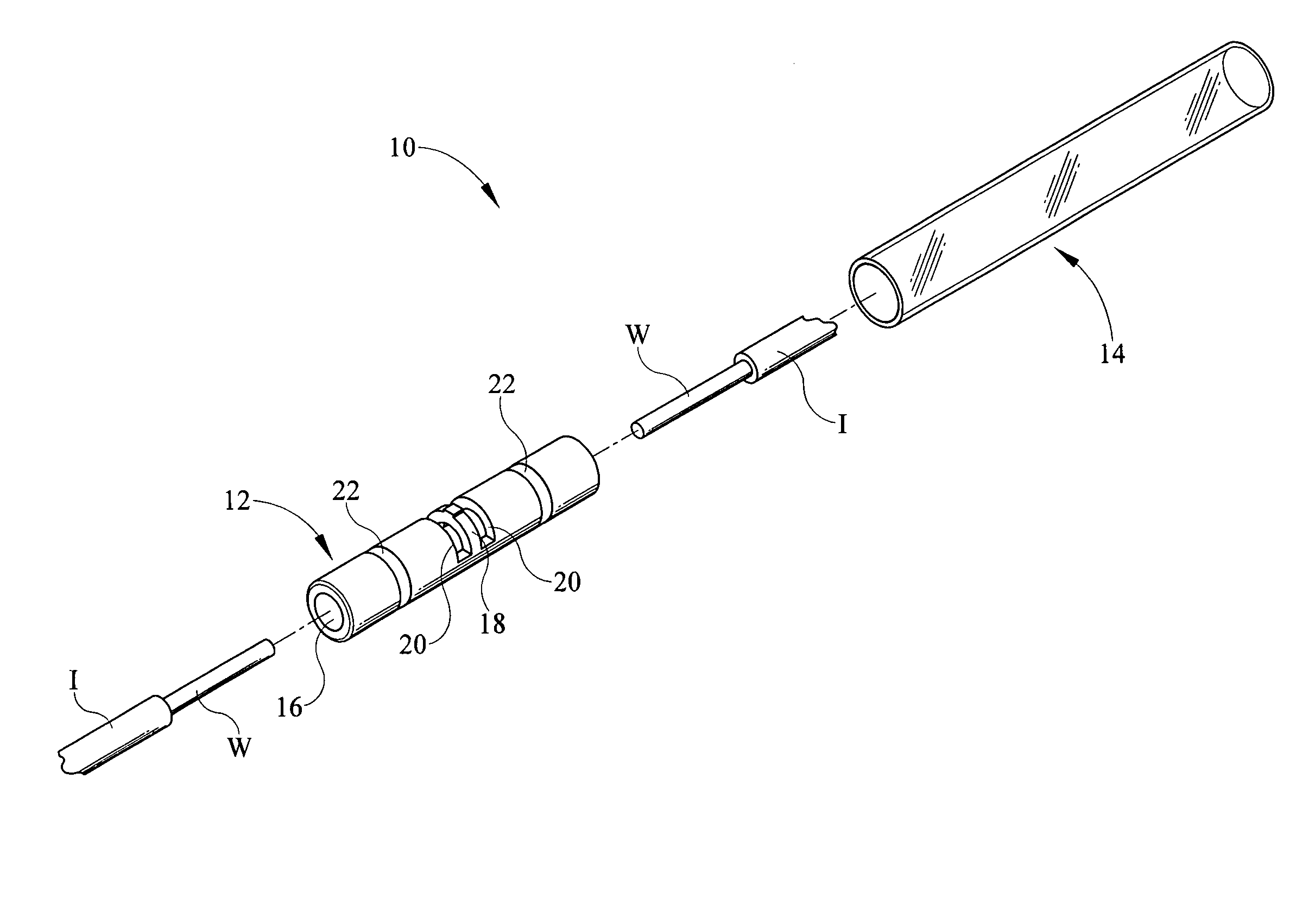
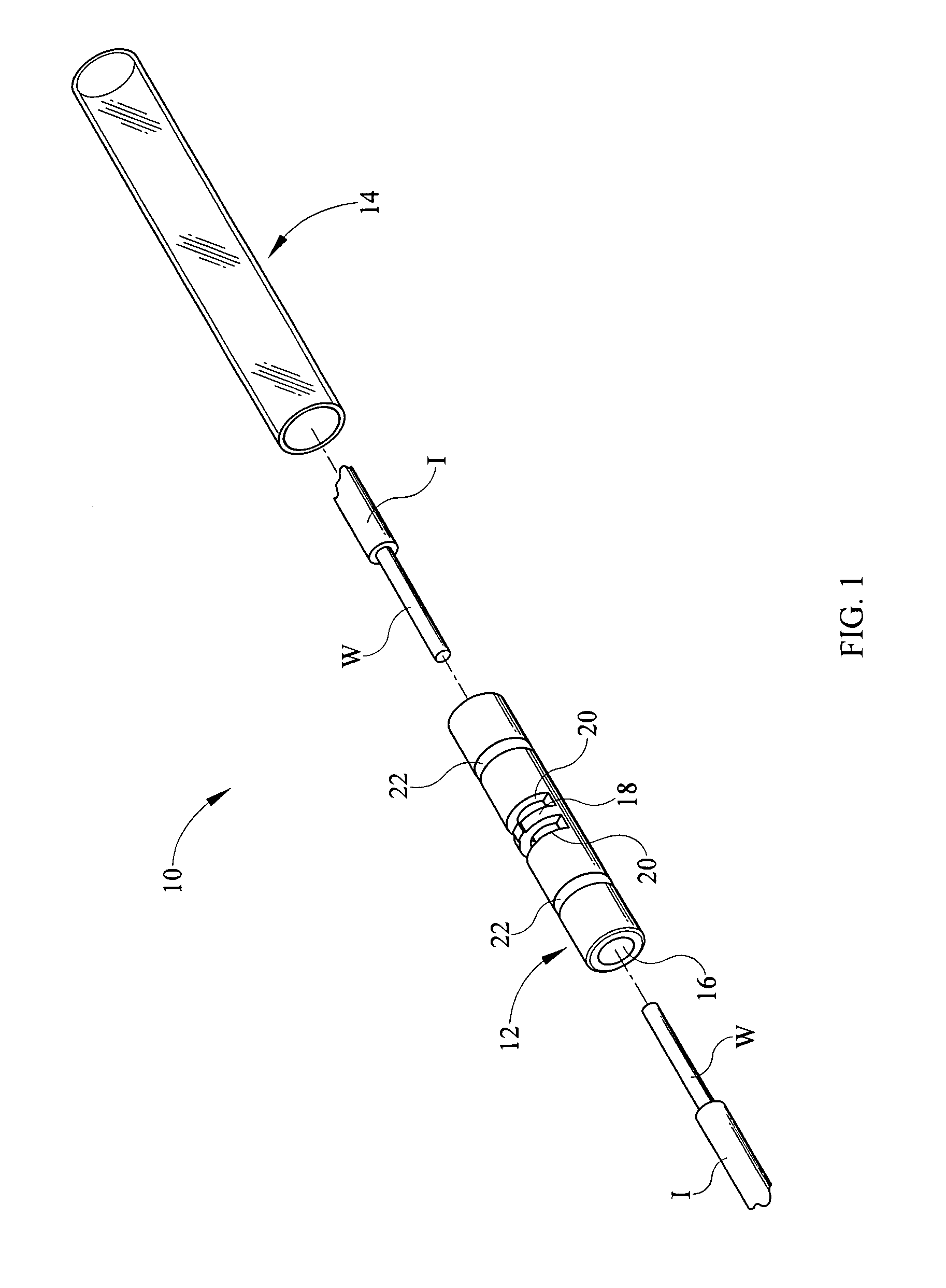
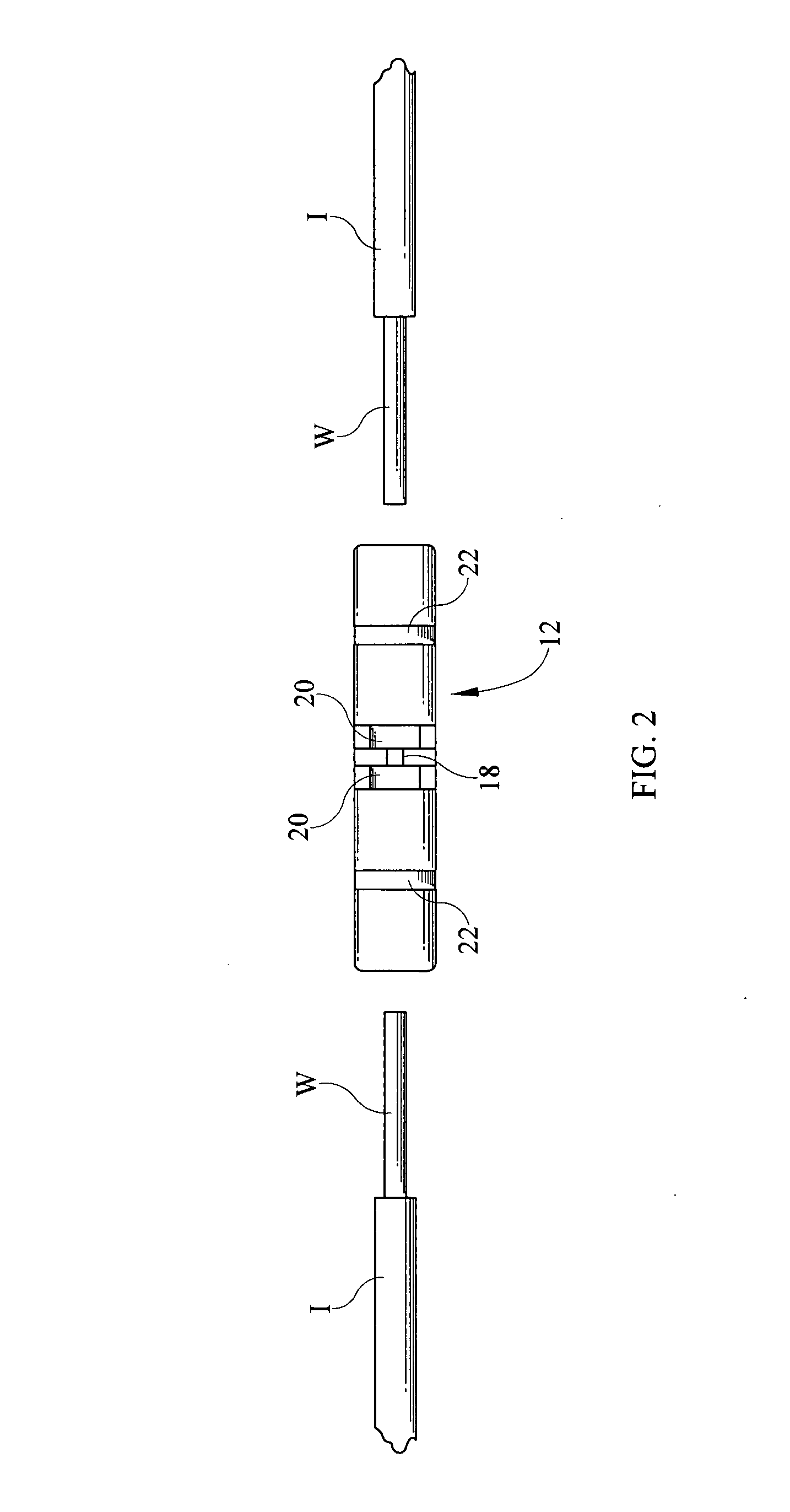
[0015]Referring now to the drawings, it is seen that the crimpable insulated electrical connector of the present invention, generally denoted by reference numeral 10, is comprised of two main components, the crimp barrel 12 and the heat shrinkable insulative sleeve 14. The crimp barrel 12, which is made from any appropriate crimping material known in the art for electrical connectors, such as tin plated copper, is a tubular member that has a hollow passage or channel 16 passing longitudinally therethrough. The diameter of the hollow channel 16 is dependent on the gauge of the wires W to be crimped by the barrel 12 such that the conductors W fit snugly when inserted into the channel 16 as more fully discussed below. Disposed (centrally or otherwise) within the channel 16 is a stop 18. Located on either side of the stop is a pair of openings 20 or cutaway sections of the crimp barrel 12 which openings 20 allow visual access into the channel 16 proximate the stop 18.

[0016]Located betwe...


PUM


Abstract

An electrical connector electrically connects two or more conductors in end to end orientation such that a bared end of each conductor is positioned within a hollow crimp barrel and crimped therein. The crimp barrel is held within a heat shrinkable sleeve that is crystal clear. Openings on either side of a stop within the crimp barrel allow for visual access into the central channel within the crimp barrel to assure proper placement and subsequent crimping of the conductors.

Description

BACKGROUND OF THE INVENTION[0001]1. Field of the Invention[0002]The present invention relates to a connector that electrically and mechanically connects a pair of conductors in an end to end orientation wherein the bared ends conductors are crimped within a crimp barrel and wherein the crimp barrel is disposed within a heat shrinkable sleeve wherein the sleeve and its inner adhesive layer are crystal clear, in particular transparent, essentially see-through.[0003]2. Background of the Prior Art[0004]Crimping two electrical conductors in end to end orientation is well known in the art. Typically, the bared ends of the two (or more) conductors are brought into an end to end orientation within a malleable and electrically conductive crimp barrel and, using a crimping tool, the crimp barrel is crimped on either side of the center of the barrel in order to assure that each conductor is crimped within the barrel. If performed properly, the crimping of the two conductors produces a solid el...

Claims


Application Information

Patent Timeline
Patent Type & Authority Patents(United States)
IPC IPC(8): H01R4/00H01R4/70
CPCH01R4/70H01R4/183H01R4/20H01R4/726H01R11/07
Inventor ENDACOTT, JOHN E.
Owner ENDACOTT JOHN E
Why Eureka
Try Eureka