Gas turbine shaft bearing system service tool and bearing system service method

a technology of gas turbine shaft bearing system and service tool, which is applied in the direction of bearing repair/replacement, bearing rigid support, machines/engines, etc., can solve the problems of too large and bulky for man-carrying portability, and achieve the effect of convenient maneuverability, convenient maneuverability and simplified bearing system servi

Active Publication Date: 2015-11-17
SIEMENS ENERGY INC
View PDF10 Cites 6 Cited by
  • Summary
  • Abstract
  • Description
  • Claims
  • Application Information

AI Technical Summary

Benefits of technology

[0009]Accordingly, an object of the invention is to create a method for servicing gas turbine shaft bearing systems and a man-portable gas turbine bearing system service tool that can be carried to a field site and installed directly in the bearing housing without the need for cranes or hoists.
[0010]Another object of the invention is to create a man-portable gas turbine bearing system service tool that can be readily maneuvered within relatively tight confines of a gas turbine support pad service space.
[0011]These and other objects are achieved in accordance with the invention by a gas turbine shaft bearing system service method and service tool that applies biasing force between a gas turbine shaft and a bearing system seal and / or the bearing assembly supporting the shaft, so that the bearing system components can be removed or installed. In embodiments of the invention the bearing service tool is coupled directly to the bearing and / or seal of the bearing system and the shaft, preferably without the need for external fixtures. A biasing force generator, such as a hydraulic unit applies a force on the bearing system components to cause the component movement on or off the shaft. Counter-biasing forces are resisted by the fixed position turbine shaft. By exerting biasing force directly between the turbine shaft and bearing system bearing and / or seal the service tool can be constructed of smaller, man portable components that are more easily maneuvered within relatively confined turbine service spaces, which are common in field installations. Elimination of the need to maneuver relatively heavy external skids with cranes and hoists simplifies bearing system service. Cost savings are realized by elimination of the need for heavy equipment to maneuver and transport known external bearing system service tool skids, and by replacing them with simpler, lighter weight bearing system service tools of the invention.
[0013]Other embodiments of the bearing system service tool feature a rotor cap adapted for coupling to a gas turbine rotor shaft concentrically therewith having an outer circumferential profile adapted for slidable engagement with a bearing system assembly bearing or seal. A first member is adapted for coupling to the rotor cap, having at least one shaft stud having a distal end coupled to the rotor cap and a shaft stud proximal end. A bearing ring is coupled to an outer axial face of a shaft supporting bearing assembly or seal of the bearing system. A second member is adapted for coupling to the bearing ring. The second member has at least one bearing rod having a distal end coupled to the bearing ring and a bearing rod proximal end. The service tool has a pivoting hub assembly having first and second hub plates pivotally coupled and radially displaceable relative to each other along a pivot axis. The first hub plate is coupled to the at least one first member shaft stud proximal end, and the second hub plate coupled to the at least one second member bearing rod distal end, so as to facilitate selective rotational indexing and concentricity alignment variances between the first and second members. At least one biasing force generating hydraulic unit is coupled to the pivoting hub assembly, for biasing the first and second members relative to each other, so as to slide the bearing system assembly bearing or seal relative to the shaft.

Problems solved by technology

The sled 52 is too large and bulky for man-carrying portability, as it must have sufficient mass to avoid inadvertent movement as the hydraulic unit exerts axial biasing force to insert or remove a bearing assembly 38.

Method used


Image

  • Gas turbine shaft bearing system service tool and bearing system service method
  • Gas turbine shaft bearing system service tool and bearing system service method
  • Gas turbine shaft bearing system service tool and bearing system service method

Examples


first embodiment

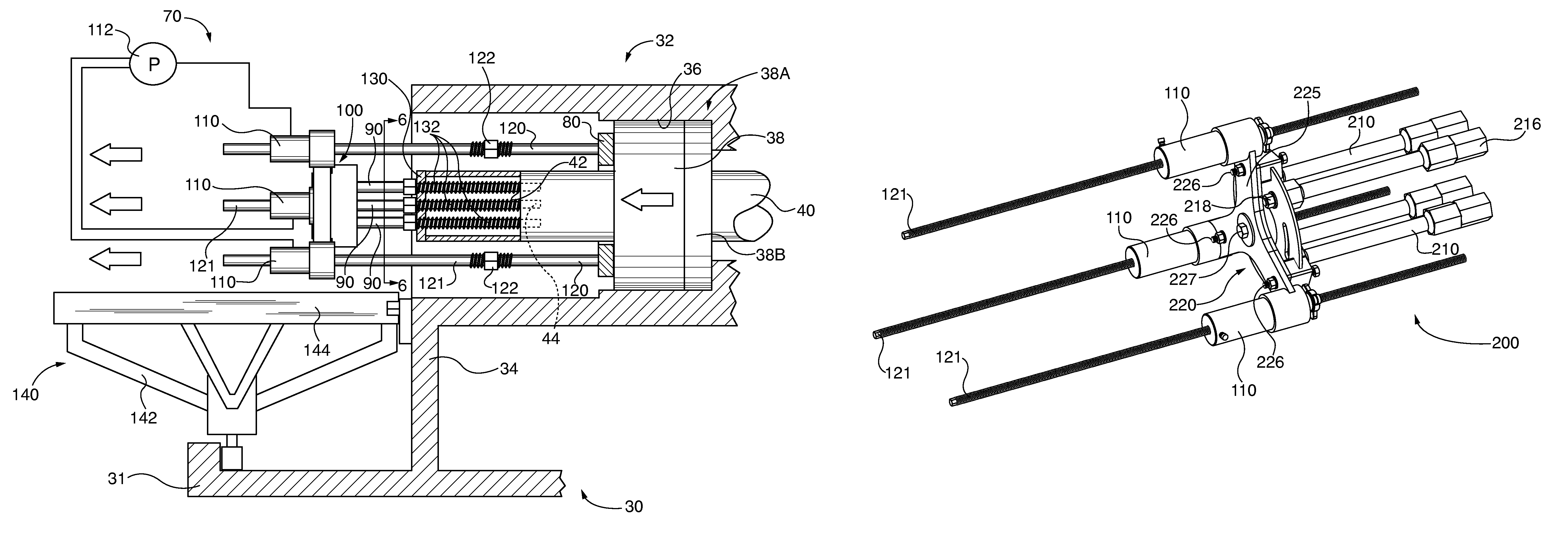
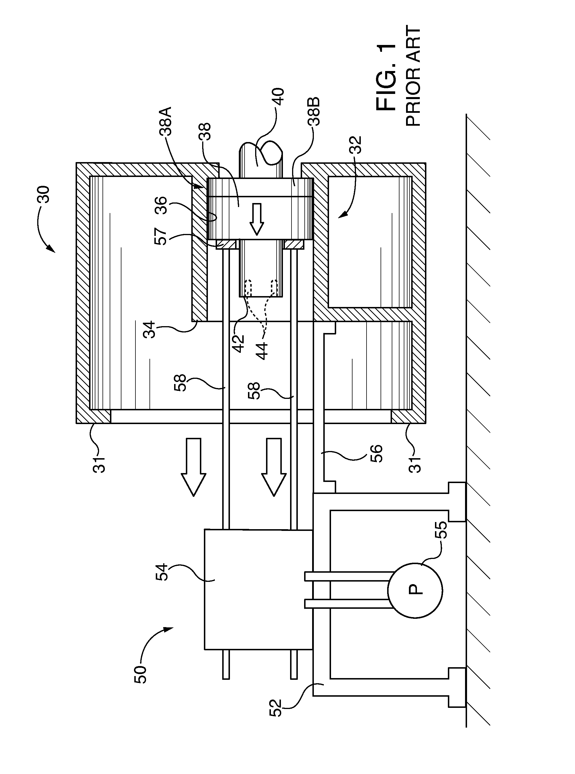
[0034]Benefits of the invention are highlighted in the side-by-side comparison of the known prior art bearing system service tool 50 of FIG. 3 to the first embodiment bearing system service tool 70 of FIG. 4. In the invention the shaft mounted service tool 70 is coupled to the shaft 40 and a bearing ring 80, without need for any other external support structure, such as the sled 52 of the known prior art bearing service tool 50. Shaft studs 90 are coupled to the rotor shaft 40 and puller hub assembly 100. Hydraulic units 100 are coupled to the puller hub assembly 100, where they are selectively pressurized by hydraulic pump 112 that in turn reciprocate the bearing puller rods 120. As the bearing puller rods are tensioned by the hydraulic units they extract the bearing ring 80 and its attached bearing assembly 38 or seal 38B of the bearing system 38A out of the bearing housing 32. In this embodiment, all of the service tool components are coupled to the rotor shaft 40 and bearing ass...

second embodiment

[0038]a bearing system service tool 200 of the invention and its methods for use are shown in FIGS. 10-20. The bearing system service tool 200 embodiment accommodates non-indexed alignment of the bearing system 38A bearing assembly 38 or the seal 38B and the rotor shaft end face apertures 44 with a pivoted or “floating” hub assembly 220 that allows coupling of the rotor shaft cap 130 and the bearing ring 80, no matter what their relative angular orientation of bolt patterns. As shown in FIG. 12 the floating hub assembly 220 provides for a range of radial play to accommodate non-concentric alignment between the bearing ring 80 and rotor shaft cap 130 which may occur during the bearing service tool 200 assembly, in additional to the rotational alignment flexibility.

[0039]In the second embodiment bearing system service tool 200 the respective shaft studs 210 distal ends 212 are coupled to a corresponding one of the extension studs 216, which are in turn intermediate the rotor cap rods ...


PUM

PropertyMeasurementUnit
biasing forceaaaaaaaaaa
axial biasing forceaaaaaaaaaa
poweraaaaaaaaaa

Abstract

A gas turbine shaft bearing system (bearing and / or seal component) service method and service tool that applies biasing force between a gas turbine shaft and a bearing system component supporting the shaft, so that the bearing system component can be removed or installed. The bearing system service tool is coupled directly to the bearing system component and the shaft, preferably without the need for external fixtures. A biasing force generator, such as a hydraulic unit applies a force on the bearing system component to cause component movement on or off the shaft. Counter-biasing forces are resisted by the fixed position turbine shaft. By exerting biasing force directly between the turbine shaft and bearing system component the service tool can be constructed of smaller, man portable components that are more easily maneuvered within relatively confined turbine service spaces, which are common in field installations.

Description

BACKGROUND OF THE INVENTION[0001]1. Field of the Invention[0002]The invention relates to gas turbine shaft bearing system service method and a gas turbine shaft bearing system service tool that facilitates axial sliding movement of the bearing system bearing and seal assemblies on the shaft during removal and installation service. The tool causes the bearing system bearing and seal assemblies to slide relative to the shaft by application of axial biasing force between the axially fixed position shaft and the bearing or seal of the bearing assembly within the bearing housing envelope. The tool is preferably operable without the need for external fixtures for application of the bearing or seal sliding biasing force, so that it can be man portable and operable within confined field installation spaces.[0003]2. Description of the Prior Art[0004]Industrial gas turbine rotor shafts are supported on bearing systems, including for example an exhaust bearing system within a bearing housing o...

Claims


Application Information

Patent Timeline
Patent Type & Authority Patents(United States)
IPC IPC(8): F01D5/00F01D25/16F01D25/28
CPCF01D5/005F01D25/16F01D25/285Y10T29/49318Y10T29/49696Y10T29/49698Y10T29/49822Y10T29/53Y10T29/5383Y10T29/5397Y10T29/53796Y10T29/53961Y10T29/53974Y10T29/53983F16C2237/00F16C35/00F16C2360/23
Inventor EDWARDS, JAMES B.CISLOIU, CEZAR
Owner SIEMENS ENERGY INC
Why Eureka
Try Eureka