Enhanced reference line tank calibration method and apparatus

a reference line and calibration method technology, applied in the direction of distance measurement, liquid/fluent solid measurement, instruments, etc., can solve the problems of increasing the price of oil and gas products, time-consuming, and still has significant problems, so as to increase the stability and increase the accuracy

Active Publication Date: 2015-11-17
SAUDI ARABIAN OIL CO
View PDF21 Cites 16 Cited by
  • Summary
  • Abstract
  • Description
  • Claims
  • Application Information

AI Technical Summary

Benefits of technology

[0014]Alternately, the surface of the tank can be a tank bottom, and the optical device can emit a substantially horizontal laser reference line substantially parallel to the tank bottom. The optical device can be mounted on a tripod to increase stability, and can level on three axes to increase accuracy. In addition, the optical device can be a narrow beam laser diode, and the linear position sensor can be a super linear position sensor, or position sensitive diode.

Problems solved by technology

Over time, the price of oil and gas products has increased.
This method, however, is very time consuming, and can be very costly because of the size of the tanks.
While the ORLM method shown in FIG. 1 is better in some ways than filling the tank and metering the fluid, as discussed above, it still has significant problems.
Although this data can be extrapolated to estimate the volume of the tank, such extrapolations may not always be accurate.
In addition, the method of FIG. 1 requires the operator 11 to be positioned on the top of the tank, which can be dangerous.
Furthermore, the use of an optical ray 10 and a horizontal graduated scale 8 to measure the horizontal offset of the tank wall 12 lacks the precision necessary to calculate accurate tank volumes.
Another problem with known ORLM methods occurs when the storage tank has a protrusion 15 extending radially outward from the tank wall, which frequently occurs, and which is shown in FIG. 2.
When this happens, horizontal offset measurements cannot be made at the top of the tank, and in some instances the inaccuracies introduced into the volume calculations by the missing measurements can be great enough to render the ORLM calibration method unreliable.

Method used


Image

  • Enhanced reference line tank calibration method and apparatus
  • Enhanced reference line tank calibration method and apparatus
  • Enhanced reference line tank calibration method and apparatus

Examples


Embodiment Construction

[0031]The foregoing aspects, features, and advantages of the present technology will be further appreciated when considered with reference to the following description of preferred embodiments and accompanying drawings, wherein like reference numerals represent like elements. In describing the preferred embodiments of the technology illustrated in the appended drawings, specific terminology will be used for the sake of clarity. However, the embodiments are not intended to be limited to the specific terms used, and it is to be understood that each specific term includes equivalents that operate in a similar manner to accomplish a similar purpose.

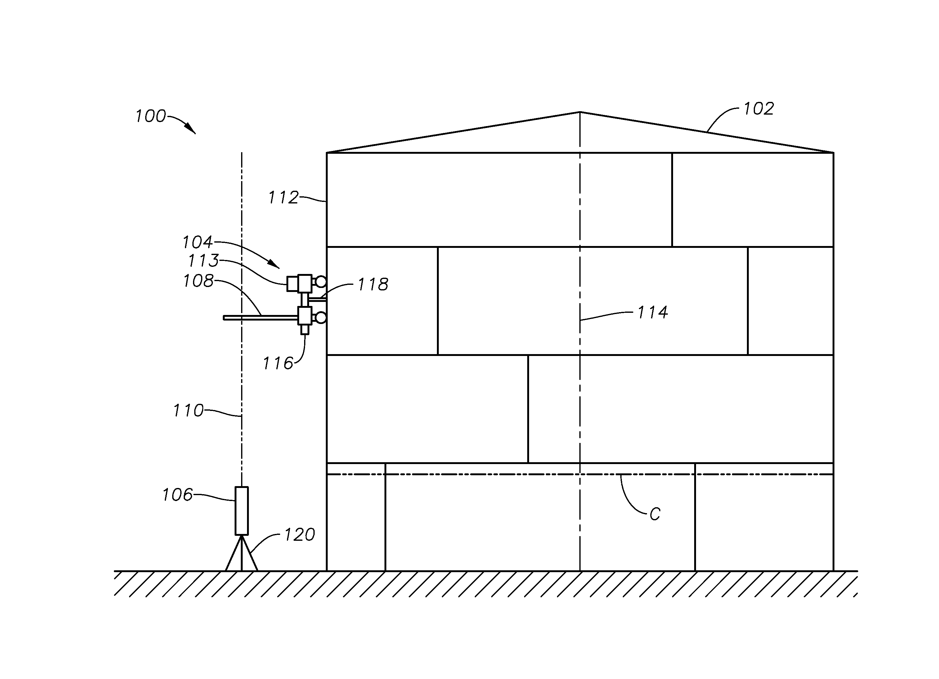
[0032]FIG. 3 is a schematic representation of a system 100 for measuring the volume of a tank that includes a tank 102, a trolley 104, a laser diode 106, and a linear position sensor 108. To measure the volume of the tank 102, the circumference of the tank 102 is first measured at a predetermined reference location using any appropriate metho...


PUM


Abstract

A system for measuring the volume of a tank, including an optical device that emits a laser beam adjacent to a surface of the tank, and a magnetic trolley selectively moveable along the surface of the tank and configured to be remotely controlled by an operator. The magnetic trolley has a linear position sensor in communication with the laser beam to determine the position of the magnetic trolley relative to the laser beam as the magnetic trolley moves on the surface of the tank. A data processor communicates with the linear position sensor to calculate the volume of the tank based at least partially on the position data collected by the linear position sensor.

Description

BACKGROUND OF THE INVENTION[0001]1. Field of the Invention[0002]The present technology relates to calibration of storage tanks. In particular, the present technology relates to calibration of storage tanks by measuring the horizontal offset of the wall of a tank relative to a vertical laser reference line.[0003]2. Description of the Related Art[0004]Over time, the price of oil and gas products has increased. As a result, the accurate measurement of oil and gas in storage has become increasingly important. Typically, oil and gas can be stored in tanks, many of which are extremely large (e.g., up to about 2,000,000 barrels in volume or more). Accurate knowledge of the volume of such tanks is important so that the owner can maintain accurate information about the amount of oil and gas in the tanks.[0005]There are a number of methods of calibrating, or measuring the volume of these large tanks. For example, one method is to fill the tank, then meter the liquid as the tank is drained to ...

Claims


Application Information

Patent Timeline
Patent Type & Authority Patents(United States)
IPC IPC(8): G01F17/00G01C3/08G01F23/72G01F25/00
CPCG01F17/00G01C3/08G01F23/72G01F25/0084
Inventor HASSELL, JR., JAMES C.
Owner SAUDI ARABIAN OIL CO
Why Eureka
Try Eureka