Apparatus and methods for object detection via optical flow cancellation

an object detection and optical flow technology, applied in the field of object detection, can solve the problem that methods may require substantial computational resources in order to solve nonlinear algebraic equations

Active Publication Date: 2015-11-24
BRAIN CORP
View PDF115 Cites 26 Cited by
  • Summary
  • Abstract
  • Description
  • Claims
  • Application Information

AI Technical Summary

Benefits of technology

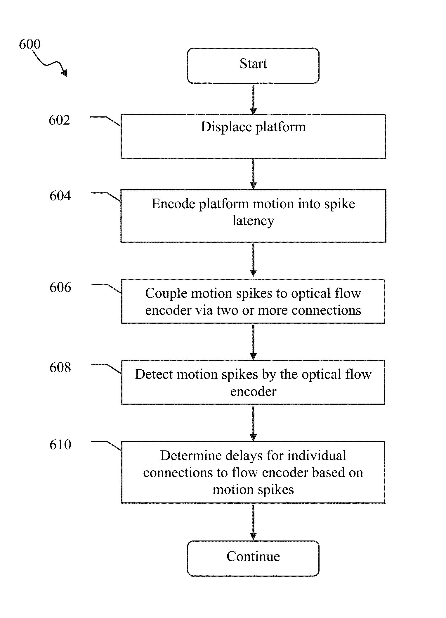
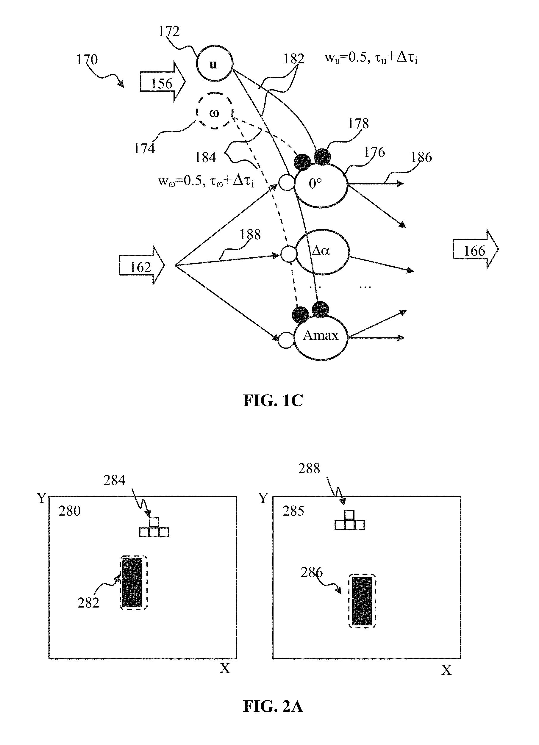
[0029]Still another aspect of the disclosure relates to a computer-implemented method of calibrating a spiking neuron network configured to determine optical flow of a robot. The method may be performed by one or more processors configured to execute computer program modules. The method may comprise: coupling a first motion encoding neuron to individual neurons of the spiking neuron network via a first plurality of connections, individual ones of the first plurality of connections being characterized by a first delay; providing an optical flow to individual neurons of the spiking neuron network, the optical flow being determined based on a first stream of pixels associated with a first motion type of the robot; and based on a plurality of responses of individual neurons of the spiking neuron network, determining a first plurality of delays of individual ones of the first plurality of connections. The determination of the first plurality of delays may eliminate an optical flow component due to the first motion type of the robot.
[0031]In some implementations, the method may comprise: coupling a second motion encoding neuron to individual neurons of the spiking neuron network via a second plurality of connections, individual ones of the second plurality of connections being characterized by a second delay; providing another optical flow to individual neurons of the spiking neuron network, the other optical flow being determined based on a second stream of pixels associated with angular motion of the robot; and based on a plurality of responses of individual neurons of the spiking neuron network, determining a second plurality of delays of individual ones of the second plurality of connections. The determination of the second plurality of delays may eliminate an optical flow component due to the rotational motion of the robot.

Problems solved by technology

However, such methods may require substantial computational resources in order to solve nonlinear algebraic equations, high frame rate, and pixel resolution to reduce noise.
Optical flow cancellation that utilizes direct estimation of motion may produce noisy results.

Method used


Image

  • Apparatus and methods for object detection via optical flow cancellation
  • Apparatus and methods for object detection via optical flow cancellation
  • Apparatus and methods for object detection via optical flow cancellation

Examples


Embodiment Construction

[0057]Implementations of the present disclosure will now be described in detail with reference to the drawings, which are provided as illustrative examples so as to enable those skilled in the art to practice the invention. Notably, the figures and examples below are not meant to limit the scope of the present invention to a single implementation, but other implementations are possible by way of interchange of or combination with some or all of the described or illustrated elements. Wherever convenient, the same reference numbers will be used throughout the drawings to refer to same or like parts.

[0058]Although the system(s) and / or method(s) of this disclosure have been described in detail for the purpose of illustration based on what is currently considered to be the most practical and preferred implementations, it is to be understood that such detail is solely for that purpose and that the disclosure is not limited to the disclosed implementations, but, on the contrary, is intende...


PUM


Abstract

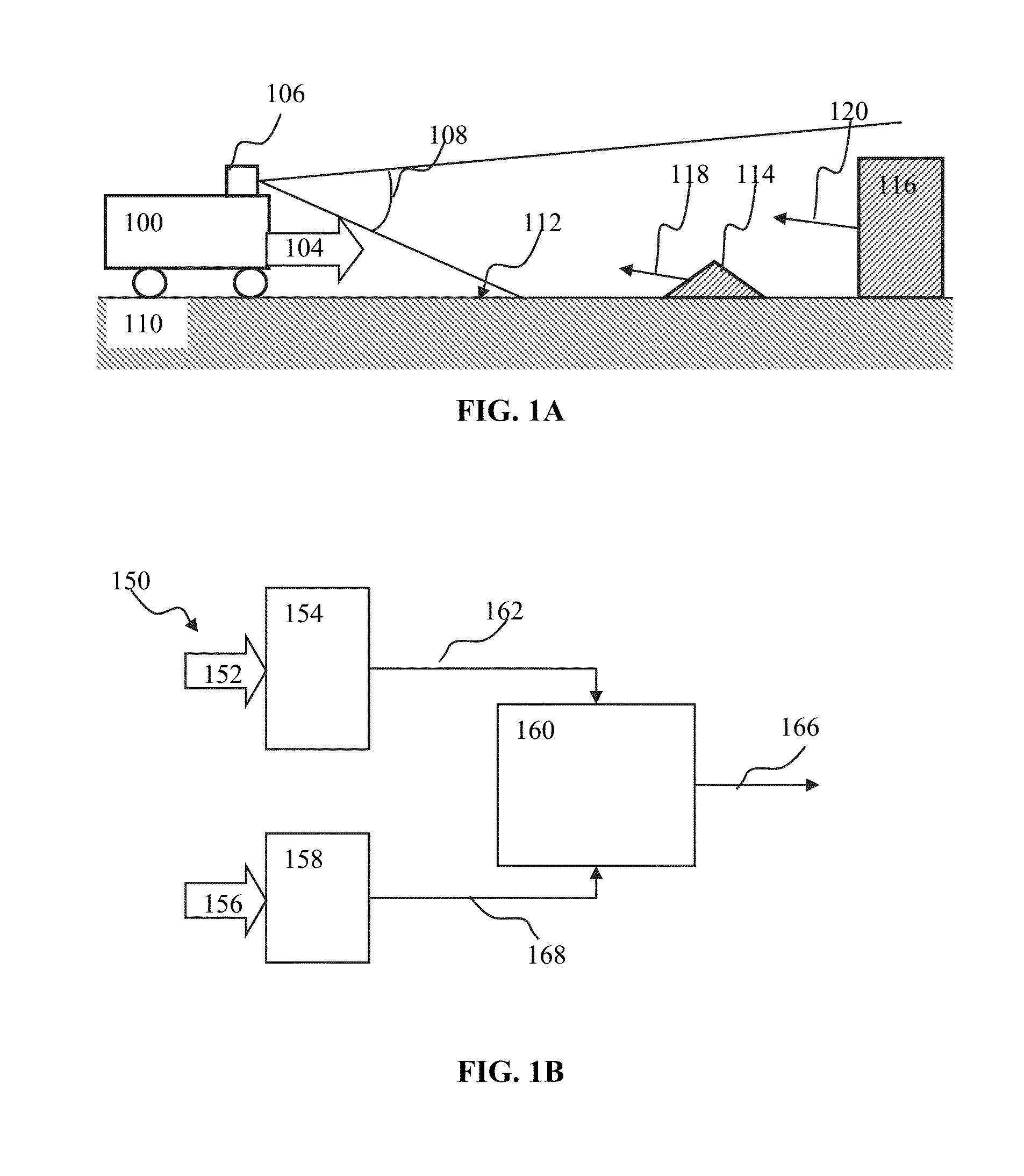
Optical flow for a moving platform may be encoded into pulse output. Optical flow contribution induced due to the platform self-motion may be cancelled. The cancellation may be effectuated by (i) encoding the platform motion into pulse output; and (ii) inhibiting pulse generation by neurons configured to encode optical flow component optical flow that occur based on self-motion. The motion encoded may be coupled to the optical flow encoder via one or more connections. Connection propagation delay may be configured during encoder calibration in the absence of obstacles so as to provide system specific delay matrix. The inhibition may be based on a coincident arrival of the motion spiking signal via the calibrated connections to the optical flow encoder neurons. The coincident motion pulse arrival may be utilized in order to implement an addition of two or more vector properties.

Description

CROSS-REFERENCE TO RELATED APPLICATIONS[0001]This application is related to co-owned U.S. patent application Ser. No. 12 / 869,573, filed Aug. 26, 2010 and entitled “SYSTEMS AND METHODS FOR INVARIANT PULSE LATENCY CODING”, issued as U.S. Pat. No. 8,315,305 on Nov. 20, 2012, co-owned U.S. patent application Ser. No. 12 / 869,583, filed Aug. 26, 2010, entitled “INVARIANT PULSE LATENCY CODING SYSTEMS AND METHODS”, issued as U.S. Pat. No. 8,467,623 on Jun. 18, 2013, co-owned and co-pending U.S. patent application Ser. No. 13 / 117,048, filed May 26, 2011 and entitled “APPARATUS AND METHODS FOR POLYCHRONOUS ENCODING AND MULTIPLEXING IN NEURONAL PROSTHETIC DEVICES”, co-owned and co-pending U.S. patent application Ser. No. 13 / 152,084, filed Jun. 2, 2011, entitled “APPARATUS AND METHODS FOR PULSE-CODE INVARIANT OBJECT RECOGNITION”, and co-owned U.S. patent application Ser.No. 13 / 689,712, entitled “APPARATUS AND METHODS FOR ENCODING VECTOR FIELD INTO PULSE-CODE OUTPUT”, filed on Nov. 29, 2012 and ...

Claims


Application Information

Patent Timeline
Patent Type & Authority Patents(United States)
IPC IPC(8): G06N3/04G06K9/40B25J13/08G06N3/02
CPCB25J13/08G06K9/40G06N3/02Y10S901/09G06N3/049G06N3/10G06T7/20
Inventor CIPOLLINI, BENJAMIN NEILIZHIKEVICH, EUGENE
Owner BRAIN CORP
Why Eureka
Try Eureka