Supercharge Your Innovation With Domain-Expert AI Agents!

Antenna device

a technology of antenna device and antenna device, which is applied in the direction of antenna device, antenna details, electrical apparatus, etc., can solve the problem of directivity problem of antenna device, and achieve the effect of decreasing the dimension of the antenna device and increasing the wireless communication angle of the antenna devi

Inactive Publication Date: 2015-11-24
CHENG UEI PRECISION IND CO LTD
View PDF3 Cites 2 Cited by
  • Summary
  • Abstract
  • Description
  • Claims
  • Application Information

AI Technical Summary

Benefits of technology

The Yagi-Uda antennae are placed on the top surfaces of second dielectric substrates, which are then fastened onto the first dielectric substrate. This reduces the size of the antenna device. The antenna device is designed to meet the requirements for high-frequency wireless communication. Additionally, the Yagi-Uda antennae are placed in different directions, which allows the antenna device to have multiple input and output characteristics. This improves the wireless communication angles of the antenna device and solves the problem of directivity.

Problems solved by technology

As a result, a directivity problem of the antenna device is solved.

Method used


Image

  • Antenna device
  • Antenna device
  • Antenna device

Examples


Embodiment Construction

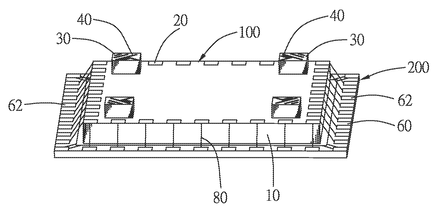
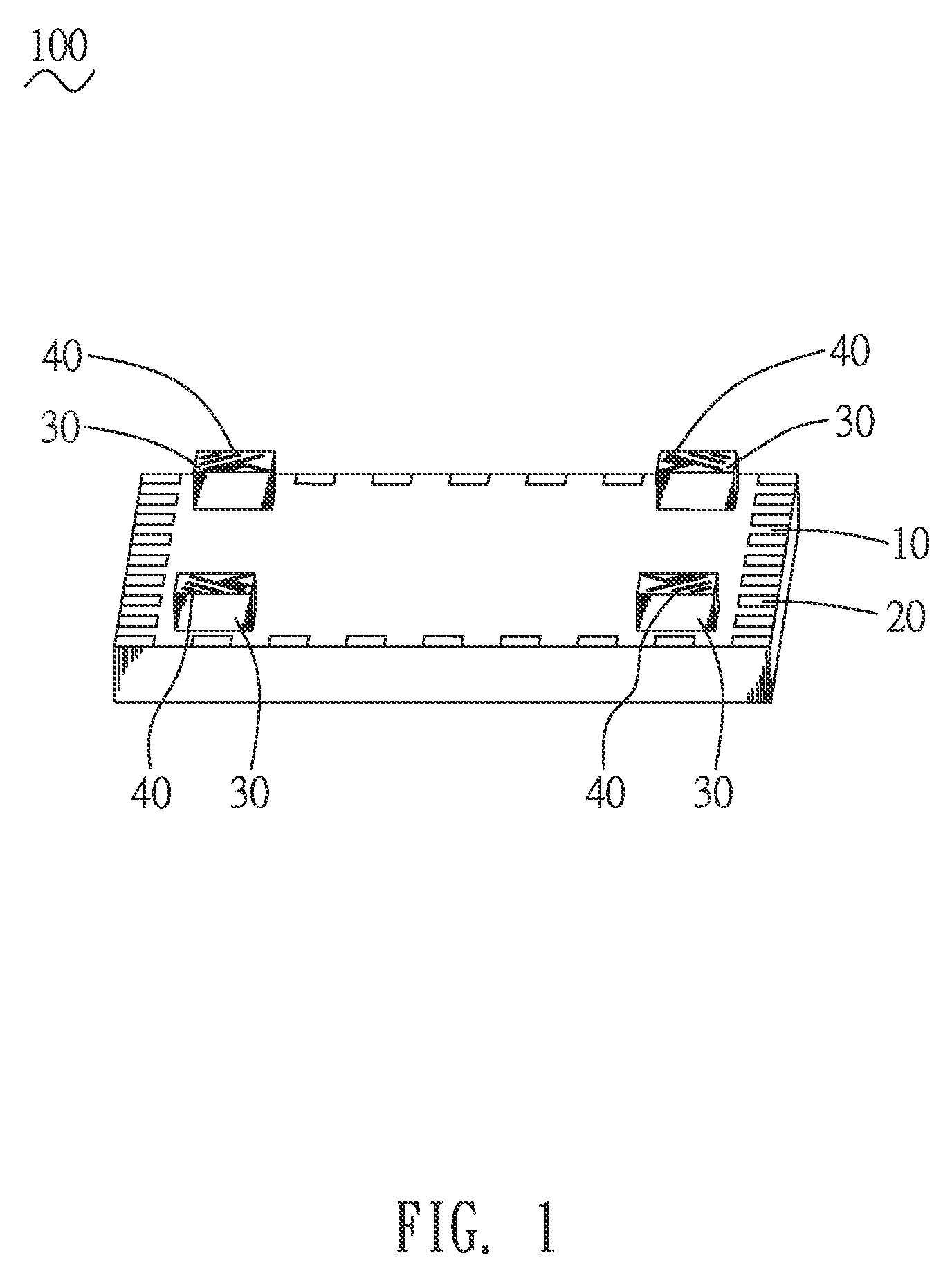
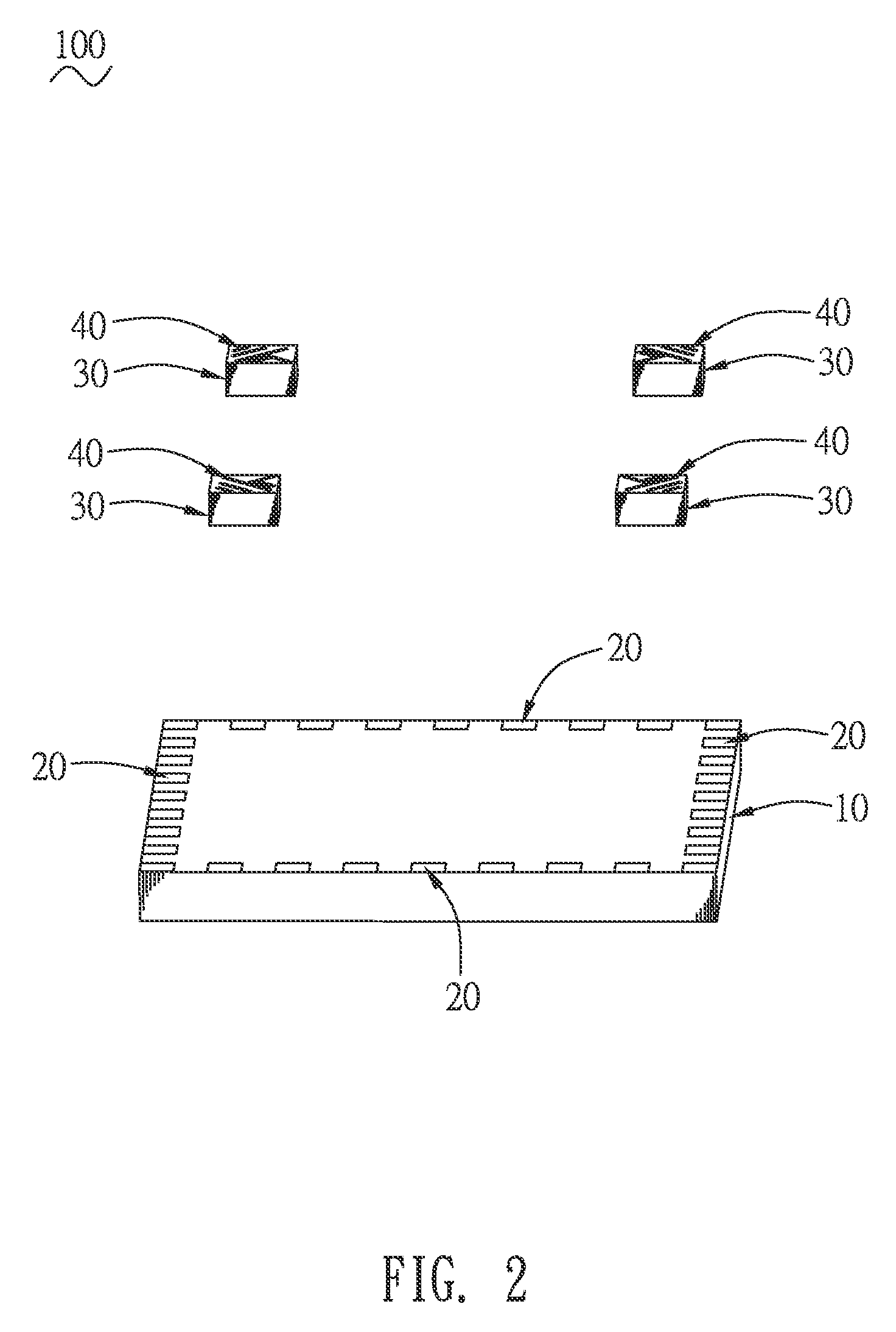
[0014]Referring to FIG. 1, FIG. 2 and FIG. 4, an antenna device 100 in accordance with an embodiment of the present invention is shown. The antenna device 100 is adapted for being applied to a wireless communication product 200 for receiving and sending high-frequency electromagnetic wave signals. The antenna device 100 in accordance with the embodiment of the present invention includes a first dielectric substrate 10, a plurality of first contact pads 20, a plurality of second dielectric substrates 30 and a plurality of Yagi-Uda antennae 40.

[0015]Referring to FIG. 1 and FIG. 2, the first dielectric substrate 10 is made of a high dielectric coefficient material. A communication circuit unit (not shown) which includes an amplifier is disposed in the first dielectric substrate 10. The high-frequency electromagnetic wave signals received and sent by the antenna device 100 should be amplified via the amplifier. The first contact pads 20 are fastened on a periphery of a top surface of th...


PUM


Abstract

An antenna device includes a first dielectric substrate made of a high dielectric coefficient material, a plurality of first contact pads fastened on a periphery of a top surface of the first dielectric substrate, a plurality of second dielectric substrates made of the high dielectric coefficient material, and a plurality of Yagi-Uda antennae respectively disposed on top surfaces of the second dielectric substrates. The second dielectric substrates are fastened on the first dielectric substrate. Each of the Yagi-Uda antennae has a drive, and a plurality of directors disposed in an outside position of the drive and spaced from an outer side of the drive. The directors are shorter than the drive, and the directors are arranged along a direction of being gradually away from the drive and gradually become shorter. An inner side of the drive defines a signal feed point.

Description

BACKGROUND OF THE INVENTION[0001]1. Field of the Invention[0002]The present invention relates to an antenna device, and more particularly to an antenna device applied to a wireless communication product.[0003]2. The Related Art[0004]Nowadays, people are in an era of wireless communication technology being used everywhere, for example, talking on cell phones, information transmission and global positioning system navigation must rely on the wireless communication technology to be completed. As is known to all, in wireless communication system which is based on the wireless communication technology, an antenna device applied to a wireless communication product is often used as a carrier for receiving and sending electromagnetic wave signals. When the antenna device sends the electromagnetic wave signals, electric currents are converted into the electromagnetic wave signals. When the antenna device receives the electromagnetic wave signals, the electromagnetic wave signals are converte...

Claims


Application Information

Patent Timeline
Patent Type & Authority Patents(United States)
IPC IPC(8): H01Q21/00H01Q19/30H01Q1/24H01Q21/28
CPCH01Q1/243H01Q21/28H01Q19/30
Inventor KO, CHING HSIANGSHIH, KAISU, JIA HUNG
Owner CHENG UEI PRECISION IND CO LTD
Features
  • R&D
  • Intellectual Property
  • Life Sciences
  • Materials
  • Tech Scout
  • Unparalleled Data Quality
  • Higher Quality Content
  • 60% Fewer Hallucinations
Learn More